Warning – Low Clearance Ahead

Nelson Moyer returns with build tips and techniques for duckunders. Click on any image here to review a larger size. Here’s Nelson with his latest tale.
Burlington Yard and Winfield Duckunder
Duckunders are to be avoided. That’s a cardinal rule of layout design. However, there are circumstances where duckunder alternatives are impossible, and my track plan presented me with no choice if I was going to model even a severely truncated facsimile of the CB&Q yard at Burlington, IA. By referring to the track plan in Part 1 of the series, it is immediately evident that the longest unbroken spaces in my basement are on the North and South outside walls, and those walls measure 16- and 18-feet, respectively. That’s not nearly long enough for Burlington, and the placement of those walls is totally wrong for a geographical approximation of the prototype.
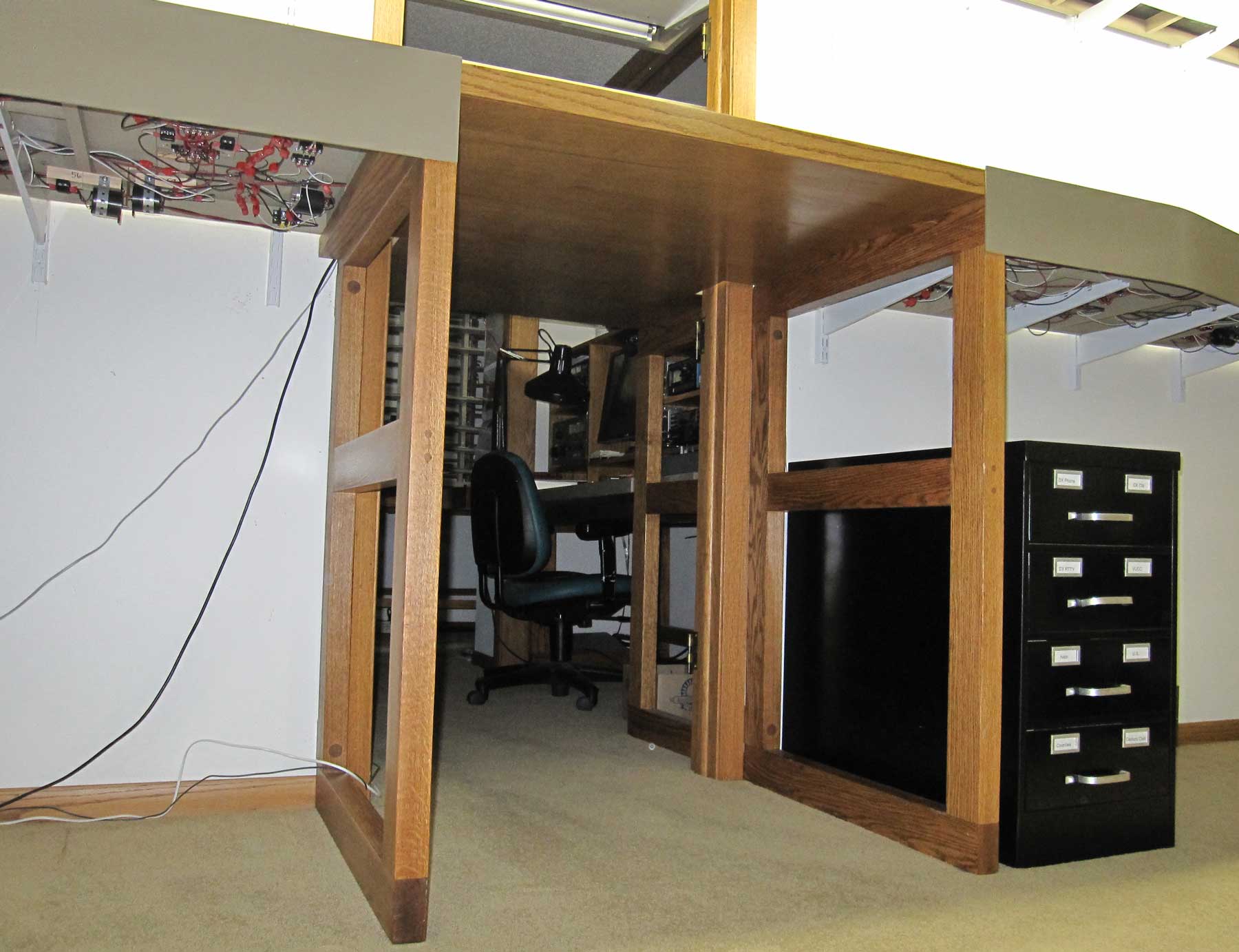
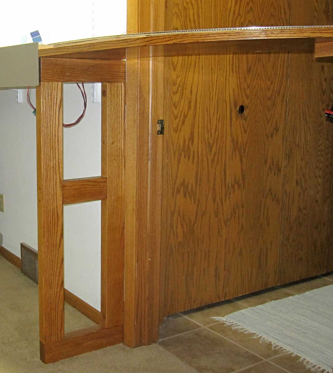
The best option for a 23-foot yard was along the family room wall from the fireplace to the laundry room door, but the doorway to the former bedroom/home office/ham radio station was approximately in the middle of that wall. The Burlington yard is 12 tracks wide on a 30-inch deep shelf. On the other side of the doorway is Winfield, with 5 tracks on a 19-inch shelf. The number of tracks and the depth of the shelves mitigated against any sort of lift up, drop down, or swinging gate. The last thing I wanted was potentially unreliable track in the middle of my largest yard. With the helix blocking the only other door to that room, a long duckunder was the only way to access the branchline. The track arrangement over the duckunder for Burlington and Winfield are shown below. The duckunder is 45.5-inches high, 35.5-inches wide, and 54.5-inches long.
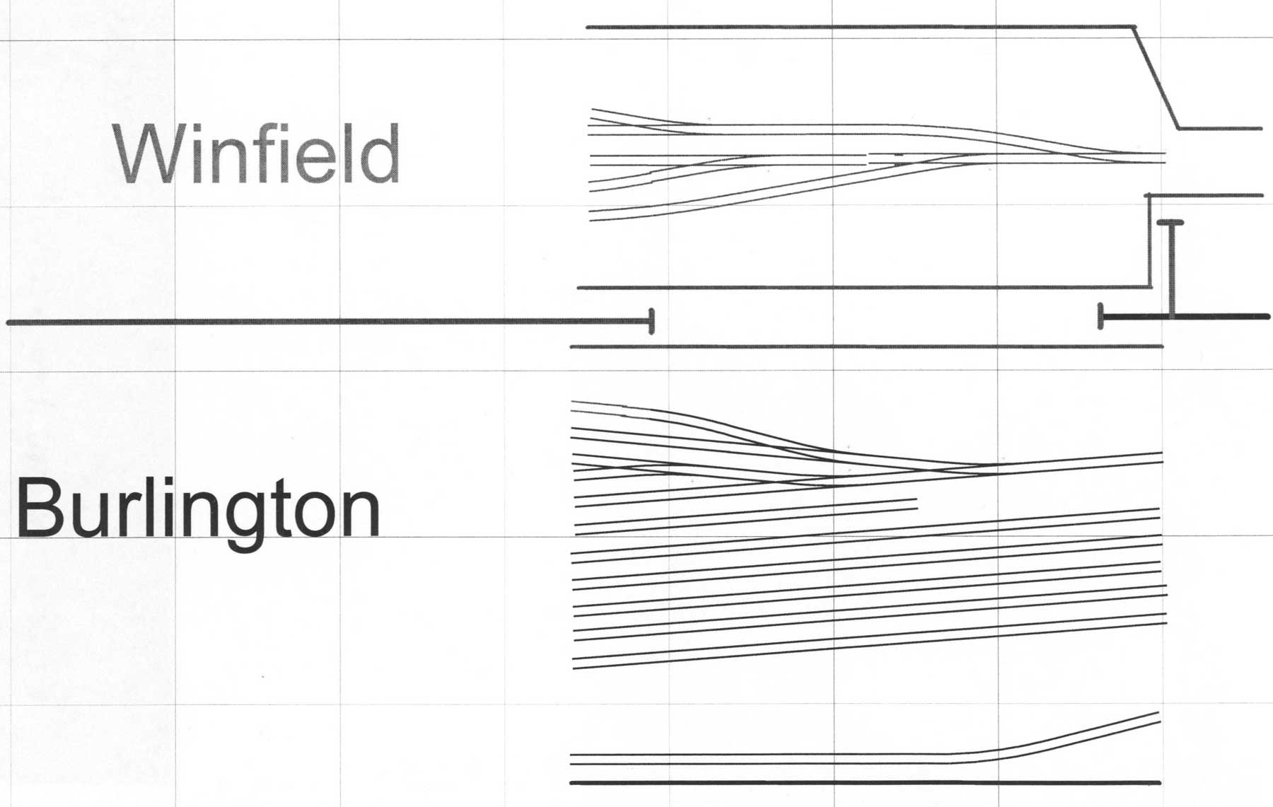
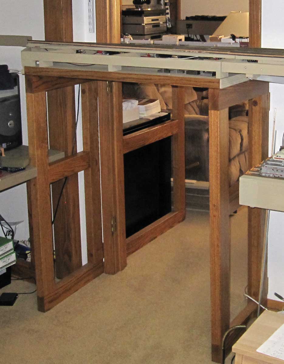
From previous experience, I find longer and lower duckunders are susceptible to a possible earthquake if someone rises up to soon while traversing its length. When the earthquake hits, I wanted to keep it on the low end of the Richter magnitude scale, thus minimizing the damage. This was accomplished by building the duckunder supports from solid oak, placing them back to back on either side of the door frame and bolting them together through the wall with long carriage bolts as shown in the concept drawing below.
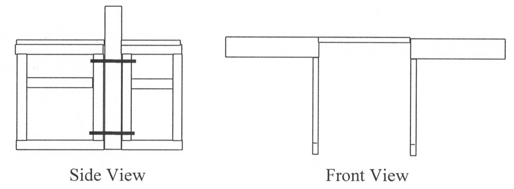
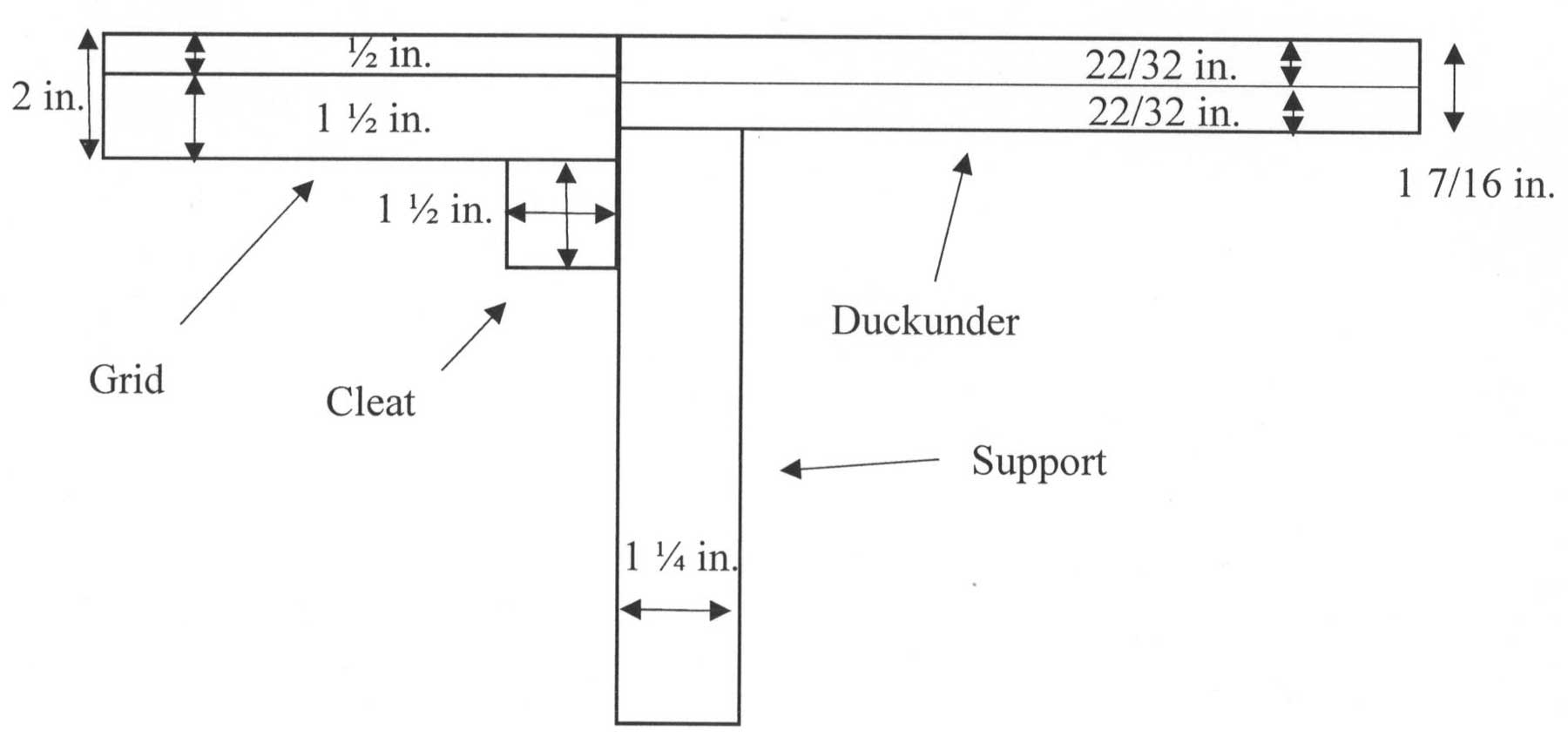
I had 1¾ x 3¼-inch oak boards custom cut at a local hardwood shop, and these boards were used for construction the duckunder supports. The design of the supports is shown below.
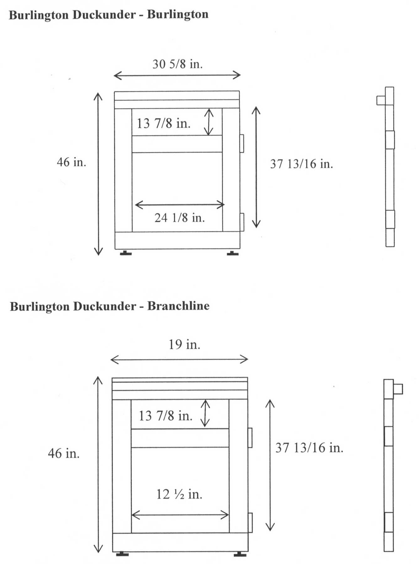
The spacers on the back provided clearance for the baseboards, and the recessed 2 x 2 inch oak cleats at near the top supported the grids on either side of the duckunder. The optimal height of the hand hold was experimentally determined. To compensate for the carpet, carpet pad, and irregularities in the basement floor, I used blind nuts and elevator bolts as adjustable feet. This allowed me to adjust the height to match the grid elevation of 46-inches. The duckunder support at the laundry room door was constructed in the same manner, except that the depth was 14-inches, reflecting the taper of the grid at the laundry room doorway. The supports were stained golden oak color and given three coats of satin polyurethane.
Mounting the duckunder supports involved clamping them to the walls on both sides of the doorway. First, I used a 1-inch Forstner bit to drill a countersink hole for the carriage bolt head and then drilled a quarter-inch pilot hole through the oak and wall. Using the pilot hole as a reference, I drilled the second countersink hole for the washers and nuts. Next, I drilled a half-inch hole for the carriage bolt. The countersink holes were filled with oak plugs.
The horizontal part of each duckunder was built separately by laminating two pieces of nominal ¾-inch plywood, producing a total thickness of 17/16-inches. Before gluing these panels together, I used a router to cut three wire channels for the DCC, accessory, and control bus wires. The grooves were 0.625-inches wide and 0.25-inches deep in the top piece and 0.625-inches wide and 0.375-inches deep in the bottom piece. The dimensions of the duckunders are shown below.
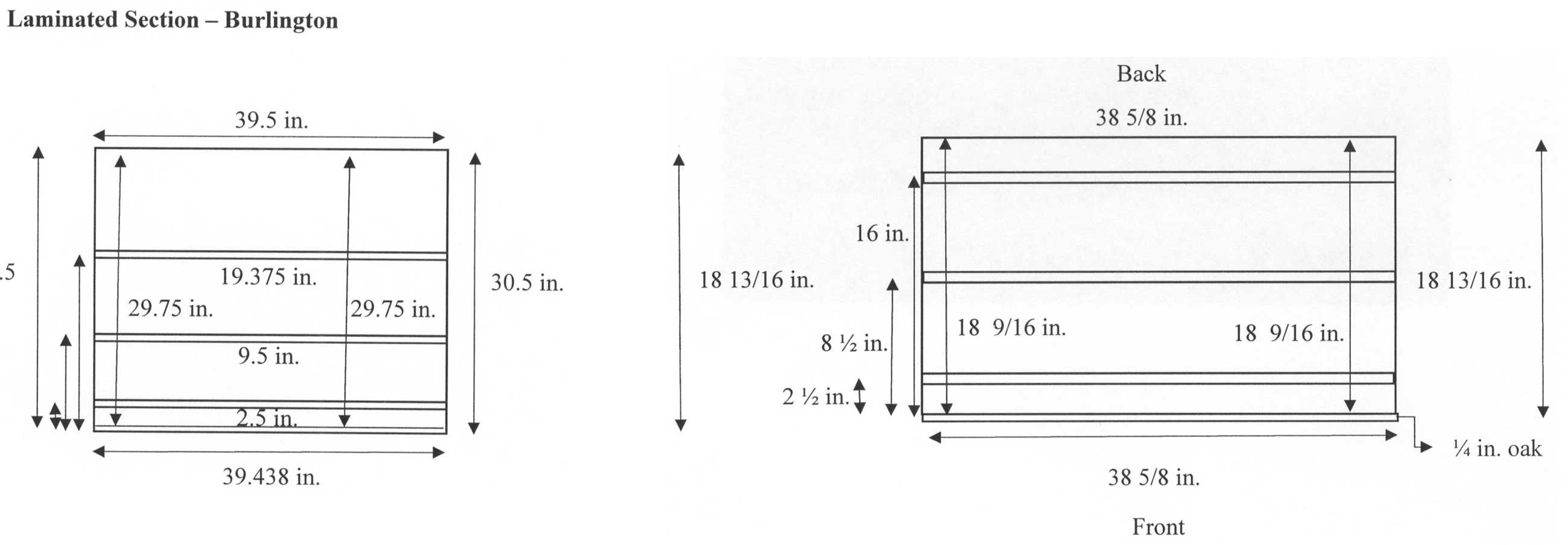
A piece of plastic tubing was placed in each wire channel, and the panels were glued together. Oak trim strips were ripped to provide edging for the front. The bottom and front edging of the duckunder were stained golden oak color and sealed with polyurethane. The top and back were painted the standard tan benchwork color
The duckunder was screwed to the supports.
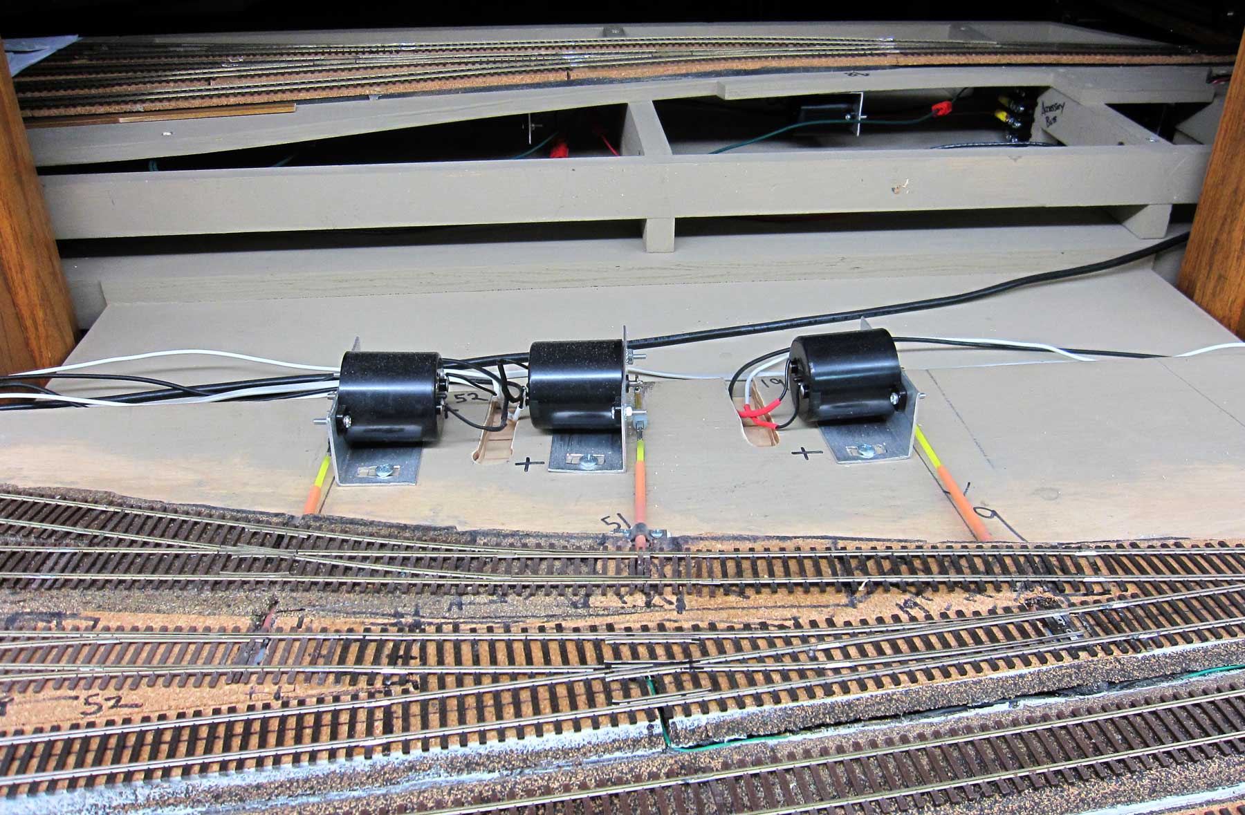
Switch motors for turnouts located on the duckunder were top mounted. They will be covered with removable buildings as scenery progresses.
The fascia does not extend across the duckunder, and the bottom of the duckunder is 45.5-inches above the carpet.
Burlington Curve Duckunder
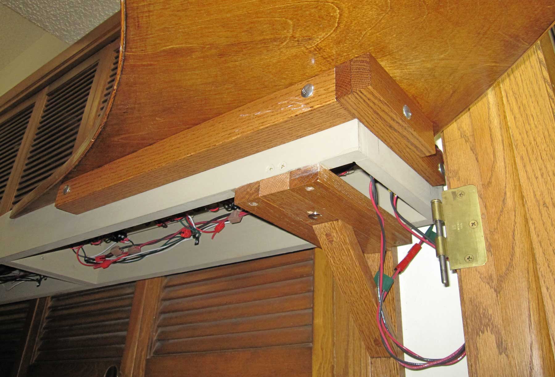
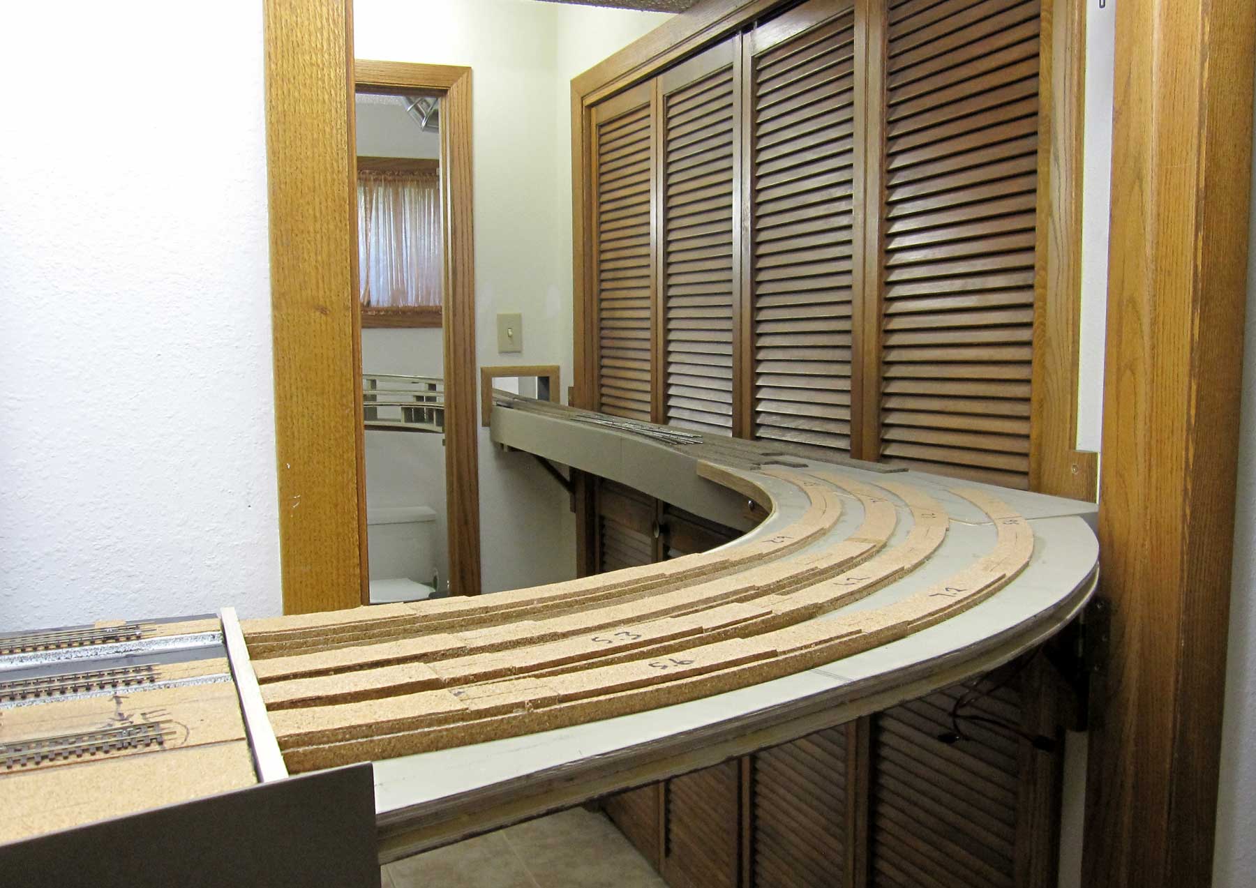
The prototype Burlington mains curve as they cross Main Street and tracks proceed Westward along Market Street toward West Burlington. My track plan duplicates this curve as tracks curve across the laundry room door, and herein lay a problem. The right of way from the end of the Burlington yard to points West and North ran across this door, through the laundry room by crossing immediately in front of the utility room, through a wall to the bathroom, across the shower, then curving across the toilet and sink, through another wall to the helix. In doing so, three tracks passing horizontally through the wall into the bathroom had to become three tracks passing vertically through the other end of the bathroom to the helix. I had to maintain access to the laundry room, utility closet, toilet, and shower (which houses my paint booth), so a series of three liftouts became necessary; the first of which also serves as a duckunder during operation. To complicate the engineering, the curved liftout/duckunder at Burlington must be supported on one end by the liftout that runs across the utility room doors. This meant that the utility room liftout had to be built and installed before I could design the curved liftout/duckunder. More about the other liftouts next time, for now I’ll describe the curved liftout/duckunder across the laundry room door. The curved liftout support is shown below. This support also anchors one end of the Burlington yard at the laundry room doorway.
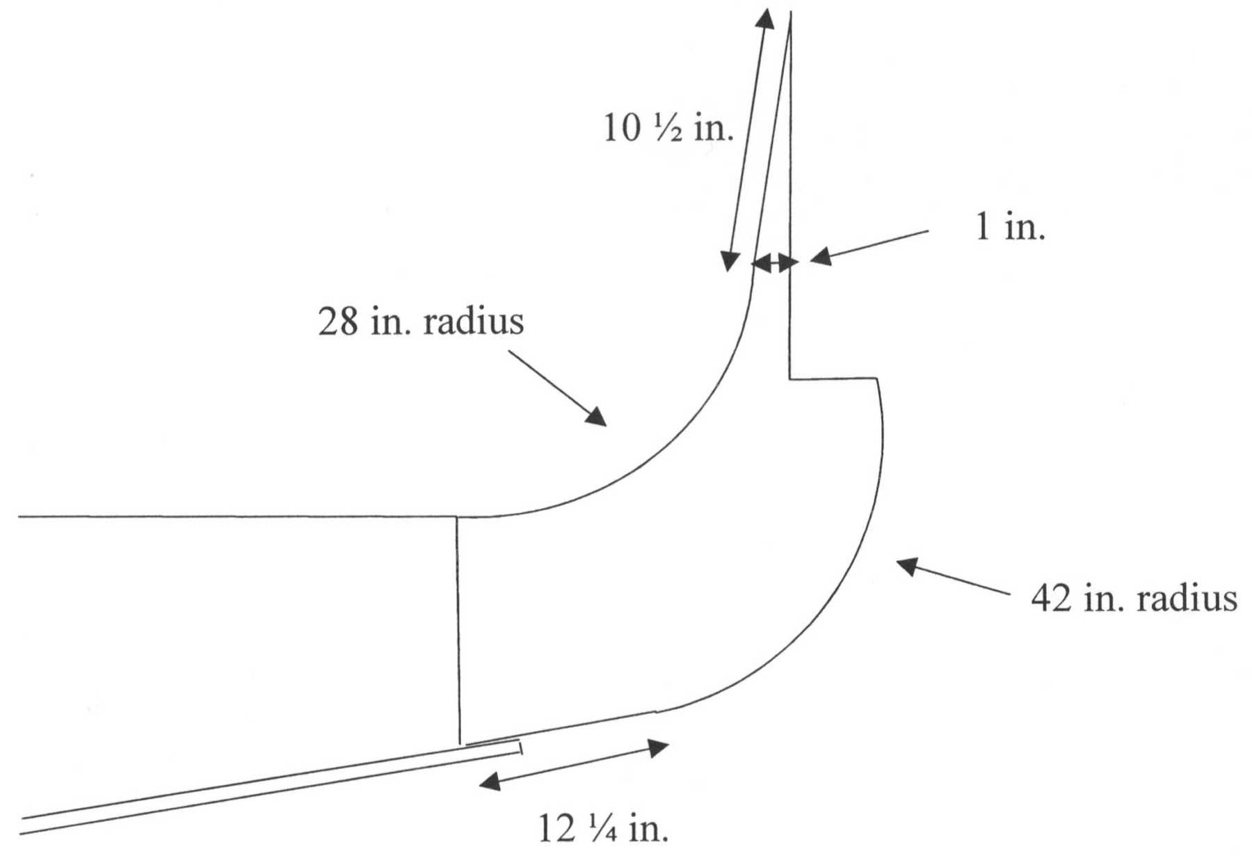
I found a large piece of cardboard and roughed out a full size template for the curved liftout/duckunder with the dimensions shown below.
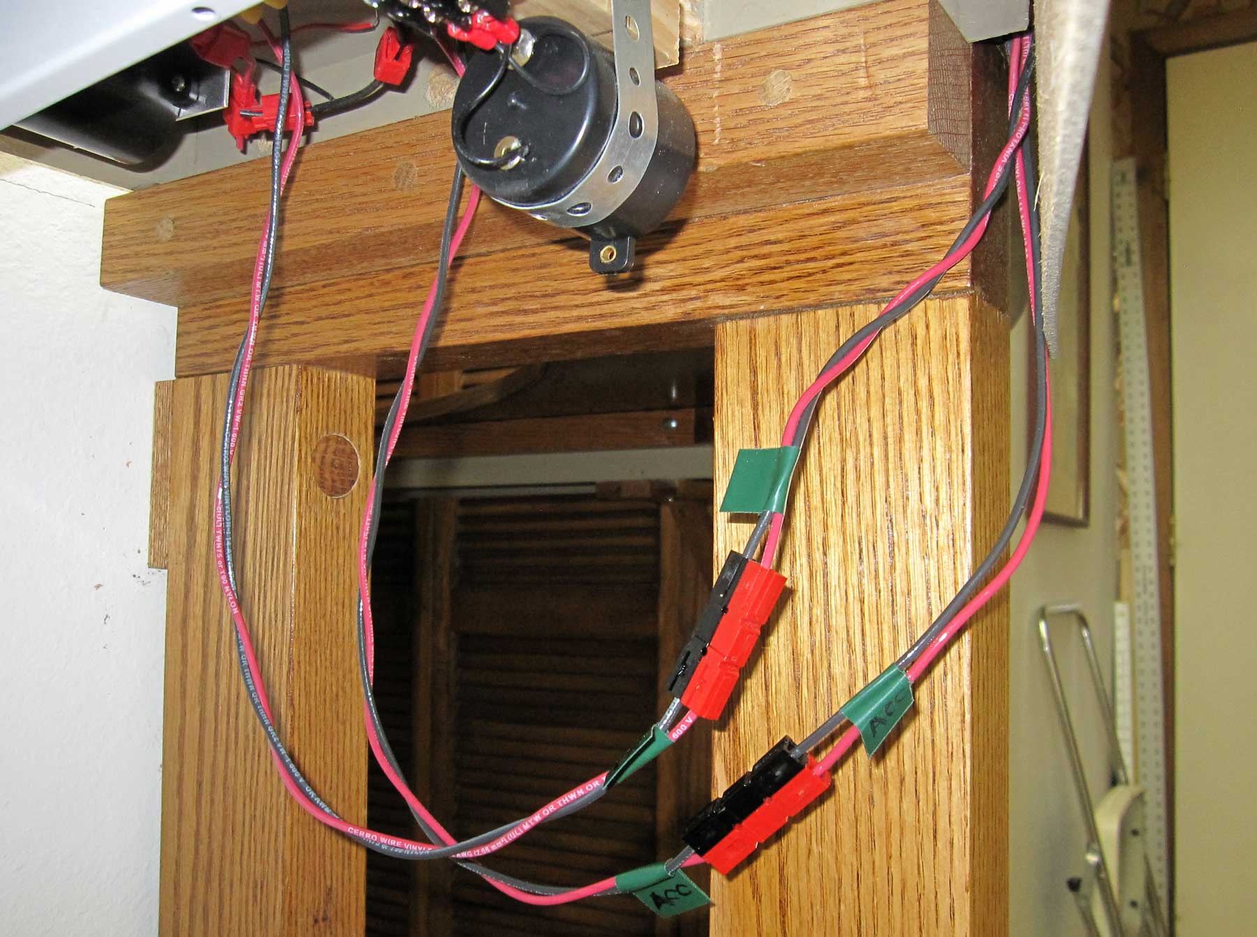
The original plan was to use two pieces of ¾-inch plywood, but for some unfathomable reason, I decided to build this liftout using half-inch plywood with quarter-inch plywood laminated to the top and bottom leaving a wire channel along the front edge. I ripped eighth-inch strips of oak for edge strips to go around all sides except the Burlington edge, which was edged with a ¾ x 2 piece of oak. The bottom and edges were stained golden oak and sealed with satin polyurethane. The top was painted with the standard tan latex paint used for all benchwork. The DCC and accessory bus wires were installed prior to adding the oak edging on the front. Anderson connectors were used as quick disconnects for all bus wires. I’ll shorten the pigtails now that construction is finished, and I know the minimum wire length required.
A piece of 2 x 2 oak was added to the utility room liftout, and the curved liftout/duckunder was set into place. Slight trimming and sanding eliminated a few binds, and the result was a snug fit. Unfortunately, I had calculated the elevation of the utility room liftout to match the thickness of two pieces of ¾-inch plywood, and now I had a laminate that was only 1-inch thick. Oooops.
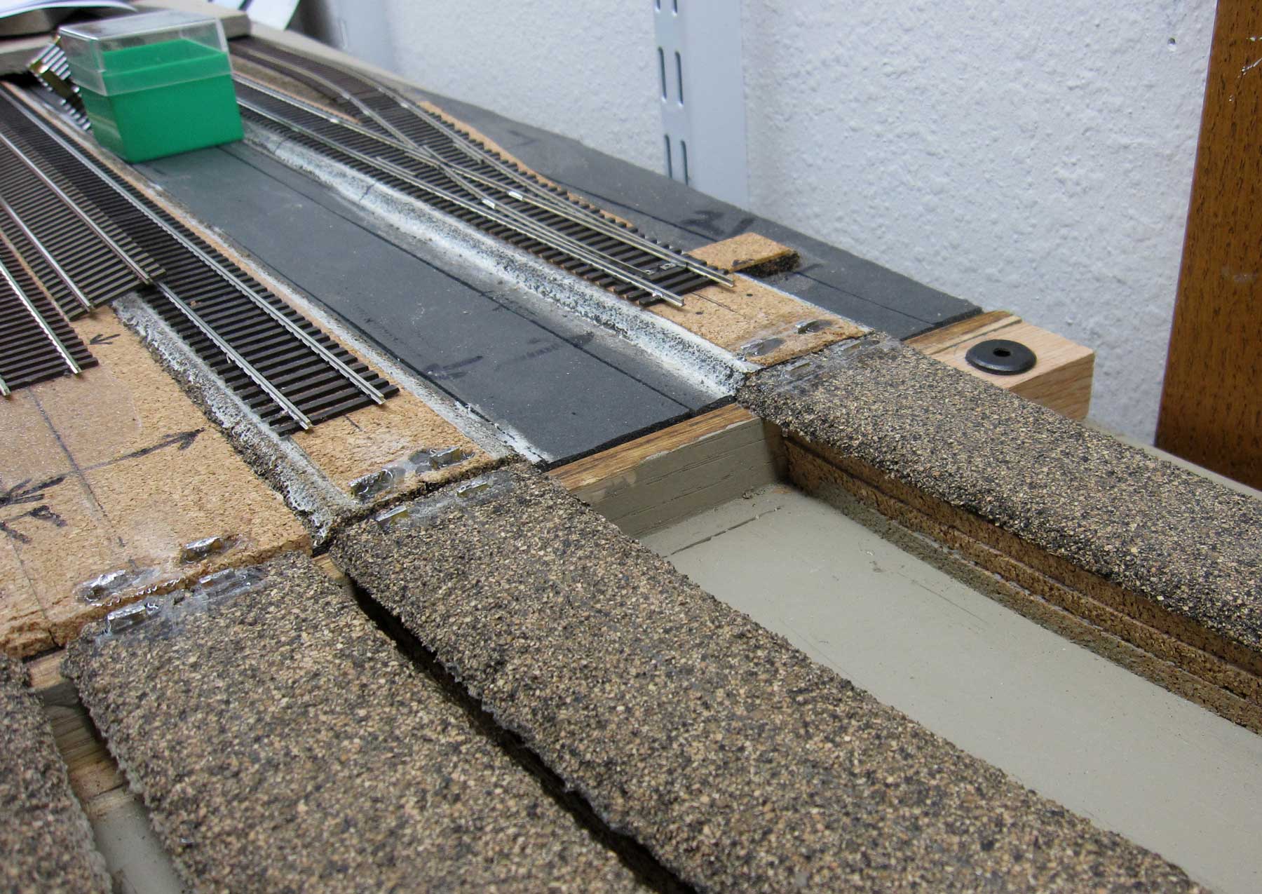
Ideally, I would have built sequentially from Burlington to the helix; however that was not practical for variety of reasons. I built Denver staging then the helix and level 1 benchwork, then the bathroom and laundry room liftouts. The connecting piece between the utility room liftout and Burlington was the final step. Had I done that in reverse, I wouldn’t have the mismatch, as any mismatch would be compensated for in the grades between the laundry room and the helix. The idea of raising the laundry room liftout and adjusting the bathroom liftout grades to accommodate the error was out of the question. The only remaining option was to make transitions for the four tracks going across the curved section. I had sheet cork for roadbed in several thicknesses, so I calculated the thicknesses and lengths required for stacked transitions and glued the cork to the plywood as shown below.
I sanded the cork for a smooth transition, then used Midwestern cork roadbed as the top layer to make the final transition from the utility room liftout to Burlington.

While this solution is far from ideal, it saved a lot of work and expense in the short term. If I find this expediency is unacceptable during operation, I’ll have to revisit the prospect of raising the utility room liftout and adjusting the grades on the bathroom liftout.
The complexity of keeping four curved tracks in alignment at the edge gaps had me stymied for a while as I sought the best way to insure reliable operation. The most acceptable solution seemed to be constructing short curved track sections on printed circuit board ties, and gluing the track sections to thin pieces of styrene so that I can ballast the removable track to blend in with adjacent scenery. After leaving the curved liftout in place for a few weeks, it became obvious that its light weight wouldn’t remain in place when bumped from below. The only way to minimize or eliminate vertical displacement was to fasten the liftout to its supports on both ends. I installed two threaded inserts on each side, and used connector bolts to hold the liftout down.
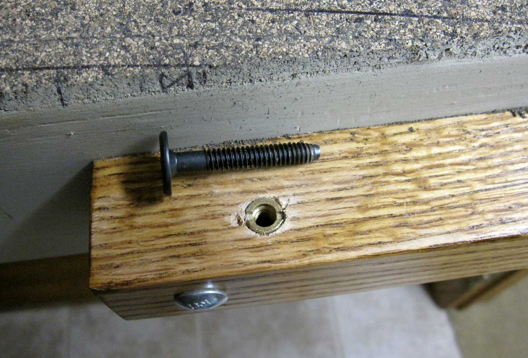
This worked on the left end where the liftout was bolted to the oak doorway support, but it was ineffective on the other end where the liftout was bolted to the long straight liftout resting on wall brackets. To provide additional rigidity, I installed one threaded insert on each end of the straight liftout, resulting in a relatively secure assembly. Operators will still have to exercise caution when navigating the duckunder, but now it’s not as vulnerable to catastrophic displacement.

12 AWG stranded copper bus wires were prepared by soldering perpendicular extension of 16 AWG stranded copper to the bus wire before installation. I drilled a 5/16 inch hole from the front edge to the back of the fourth track, and then I measured the track distances and drilled ¼ inch holes at an angle toward the front edge. The resulting wire harness was completed by fishing 22 AWG solid feeder wires through the angled holes to the front edge, where they were soldered to the extension wire at appropriate intervals to match track dimensions. Pulling the feeders back out pulled the extension wires into place, and positioned the bus wires in the wire channel. I cut the feeder wires to proper length, and routed them to the tracks through a slot cut in the cork roadbed. The ends of the feeder wires were bent into a U-shape, positioned under the rails, and then soldered to the bottom of the rails.
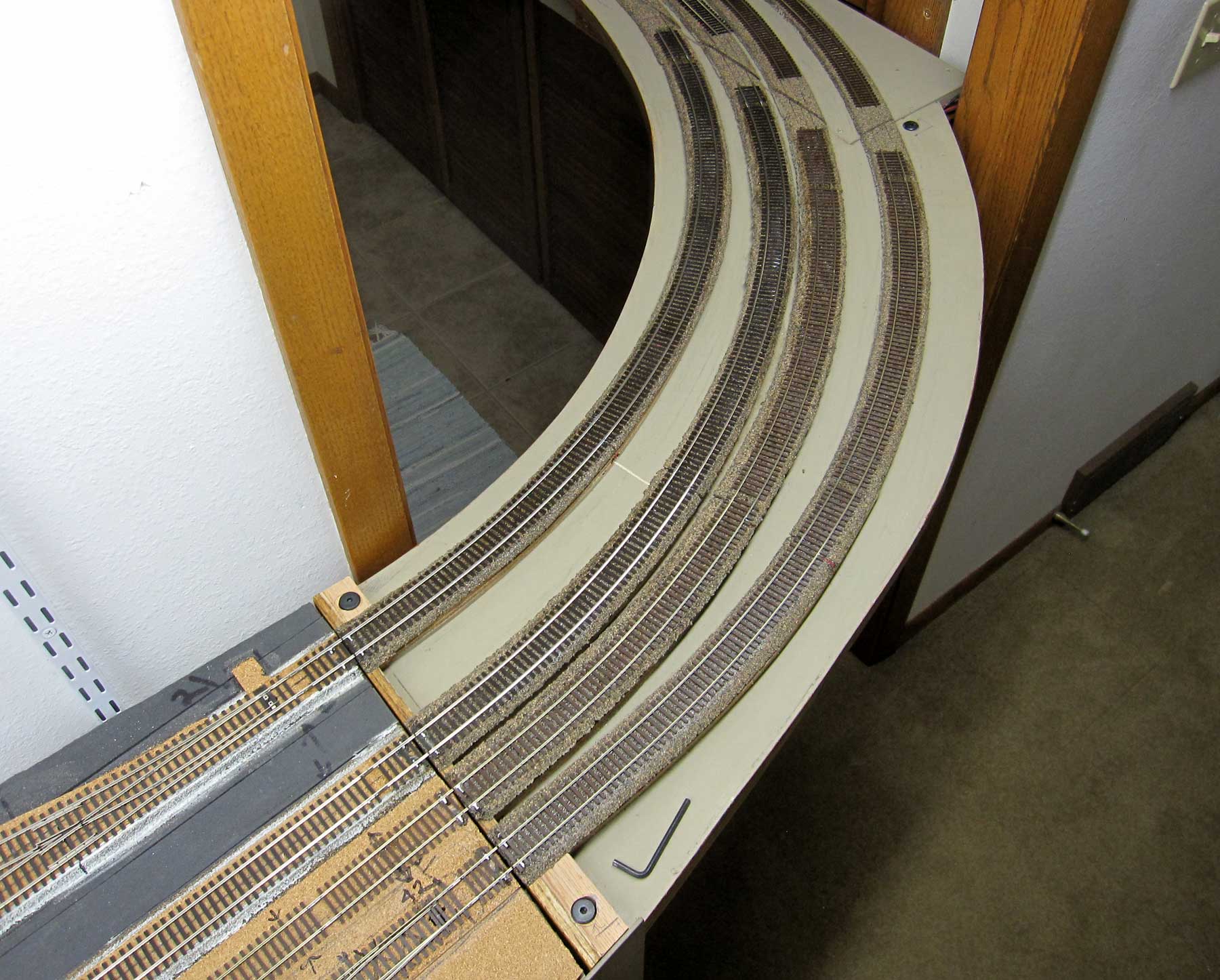
As seen in the image above, track was installed with a space across the curved gaps for short removable track sections. The straight gaps were cut after rails were soldered to the stabilizer stubs.
I’ll report on the methods used to construct the other three liftouts, removable track sections, and rail stabilizers in the next post.
Thank you, Nelson, for sharing your duckunder construction details. Here are links to Nelson’s previous layout posts.
Layout Design with Nelson Moyer – Part 1
Overcoming Adversity – Part 2
Roadbed and Track – Part 3
Layout Wiring – Part 4
Layout Lighting – Part 5
Building the Helix- Part 6
We will continue with more progress in upcoming blog posts.
Questions and comments can be posted below. Please follow the instructions so your comment can be posted. All comments are reviewed and approved before they appear. To subscribe to this blog, enter your info for a comment and check the last box to notify of new posts by email. Share the blog link with other model railroaders.
Nelson,
One thing that my career in operational test taught me is that there are no absolutes. That said, there’s a risk/cost tradeoff for all of our choices. Procedural mitigation measures are just as valid as engineered systems solutions and are useful for your non circuit protected liftouts. Something as simple as a checklist procedure for blue flagging the master power switch before removing one would be a no cost means of “minding the gap” and that physical reminder by the switch can get you back in the groove after a long layoff. Another thing to consider on your circuit protected liftout is many decoders now have keep alives. Great for their intended function of getting over unintended dead spots, but the work just as well through intended ones too. It’s impossible to idiot proof anything because we keep making better idiots. All we can hope for is to learn enough from others to only make original mistakes and your sharing of your journey is helping the rest of us on our own. Thanks
Much as I admire what you have done in creating rigidity, etc, the chance of an “earthquake” can be significantly lessened by raising your benchwork. Judging from a light switch in one photo, yours appears to be about 40″ or so. I have a duck under entering my layout that is about 52″. It is a lot easier to navigate and also places the layout closer to eye level – much nicer to enjoy.
I know there are trade-offs with going higher, one being poorer reach and visibility over wider benchwork such as a large yard. But it is an option, though maybe too late for you.
Jim, had you read the second paragraph carefully, you would know that the height of my duckunder is 45.5 in. from the carpet to the bottom. The light switch will be covered by the backdrop, so it’s not in use. Had you read part two of this series, you would know that the branchline has three levels, two of the three levels traverse the doorway, and there is an HVAC plenum along the ceiling that crosses the doorway with a maximum floor to ceiling height of 81 inches. That dimension was the limiting factor in establishing the heights of Burlington and levels 1 and 2 of the branchline. I selected the elevations I used after experimentation, and they are optimized to accommodate the branchline elevations as well as the elevation at Burlington. It’s important to read my posts in context to gain a full understanding of my space limitations, and how I’ve dealt with them in pursuing my dream.
Timely! My layout will probably have a duckunder/gate (for when I just want to sit and watch the trains go around.)
I want to do ‘electrical interlocking’ so the track on either side of the gate is dead if the gate is not in position.
David, Bill Darnaby published a circuit for interlocking liftouts that I used on one of the four liftouts on my layout. I don’t remember the reference, but I’ll describe it in my next post on my liftouts. I didn’t use it on the other three liftouts because they are only removed a few time each year, and the railroad will never be powered while they’re out of place.