Nelson Moyer returns with another installment on his layout developments.
With a substantial part of the benchwork in place, I turned my attention to the right of way. I want bulletproof track. I’ve operated on layouts where derailments are common, and I find that they steal my joy. I want quiet track, so that I can hear decoder sounds at reasonable levels without blowing out my operator’s hearing aids.
After reading the roadbed test article in the 2009 How to Build Realistic Reliable Track, I decided to conduct my own tests on sound deadening roadbed combinations. I built a test track with a series of curves from 26 to 36 inch radius on two-inch centers on several combinations of roadbed with and without foam tape underneath. My findings confirmed the published studies – foam tape and cork were indeed the quietest combination when both the cork and the track were glued down using construction adhesive. The foam tape is self-sticking. The key is that this method of tracklaying does not require spikes that will transmit sound waves to the sub-roadbed, which acts as a reverberator when spikes are use. As long as ballast is terminated on the foam, it won’t transmit sound, either.
I wanted variation in rail size between the main line and the branch line spurs, so I decided to use Walthers-Shinohara code 83 track on the main through Burlington and in all of the staging yards, Micro Engineering code 70 track in the Burlington yard and on branch line main, and Micro Engineering code 55 track on the branch line spurs. The track plan calls for several curved turnouts to maximize the length of branch line towns, and Micro Engineering does not make curved turnouts. The workaround to this problem was to use code 70 curvable turnouts from Shinohara. I used Walthers-Shinohara transition track sections to go from code 83 to code 70 rail, and Micro Engineering transition rail joiners to go from code 70 to code 55 rail. To keep things compatible, I used the rail joiners from the track manufacturer, i.e. Walthers for Walthers, Micro Engineering for Micro Engineering, and Shinohara for Shinohara.
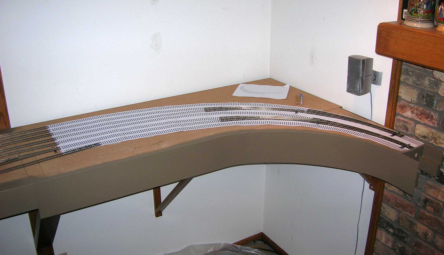
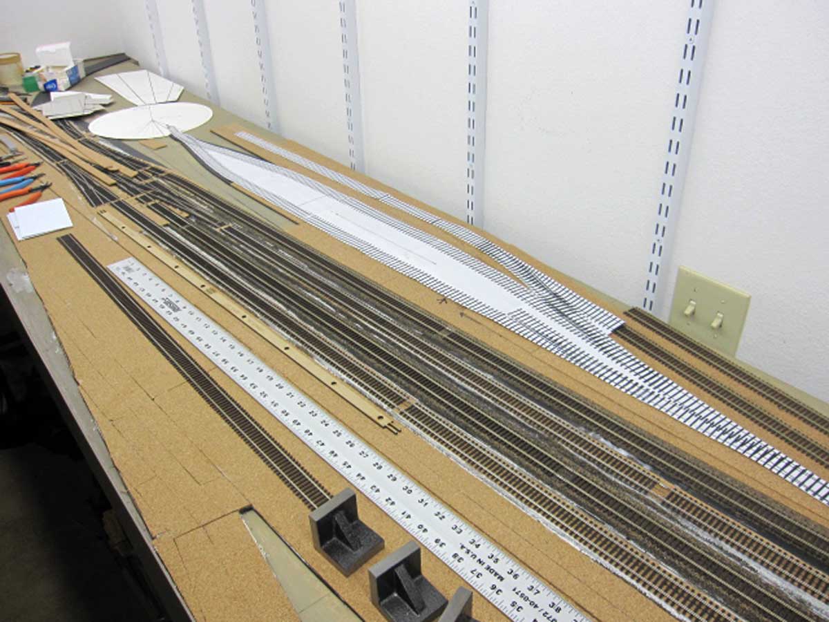
I use full size printouts of my track plan from 3rdPlanIt to lay out complicated track sections. The yard throat to Chicago uses four #8 curved turnouts, and I wanted to get those down right the first time. Gluing track can be unforgiving if you mess up, and you risk damage to the track if you have to pry it up with a putty knife and try again.
All track on the layout except the helix, staging yards, and connecting tracks without scenery have a sound insulating layer of 3/16 inch foam tape under the cork. I use both Midwest cork strips and sheet cork in various thicknesses for roadbed. The mainline cork is a quarter inch thick. The staging yards are covered with quarter inch sheet cork. Burlington yard tracks are stepped downward from quarter inch cork on the main, to 3/16 inch cork on the arrival/departure tracks and depot siding, to eighth inch cork on the yard tracks. When combined with the reduction of rail size from code 83 rail on the mains and code 70 in the yard, the gradations are noticeable. I ordered the sheet cork online from Bangor Cork.
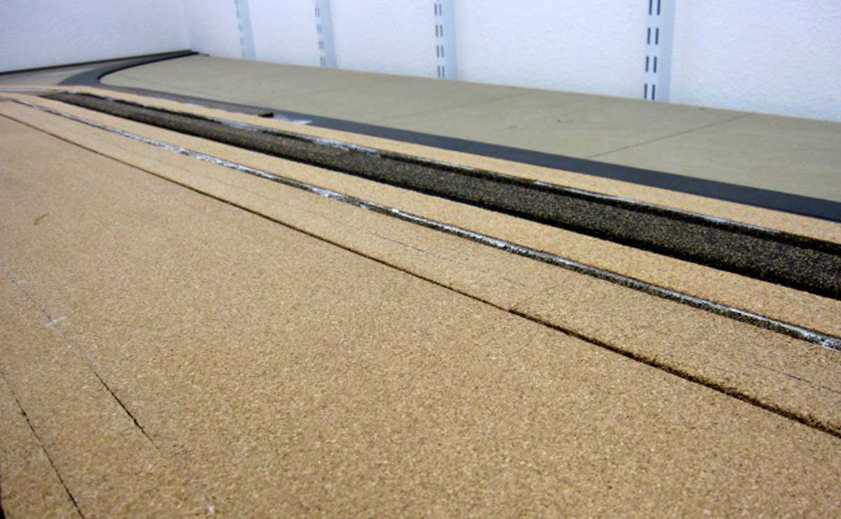
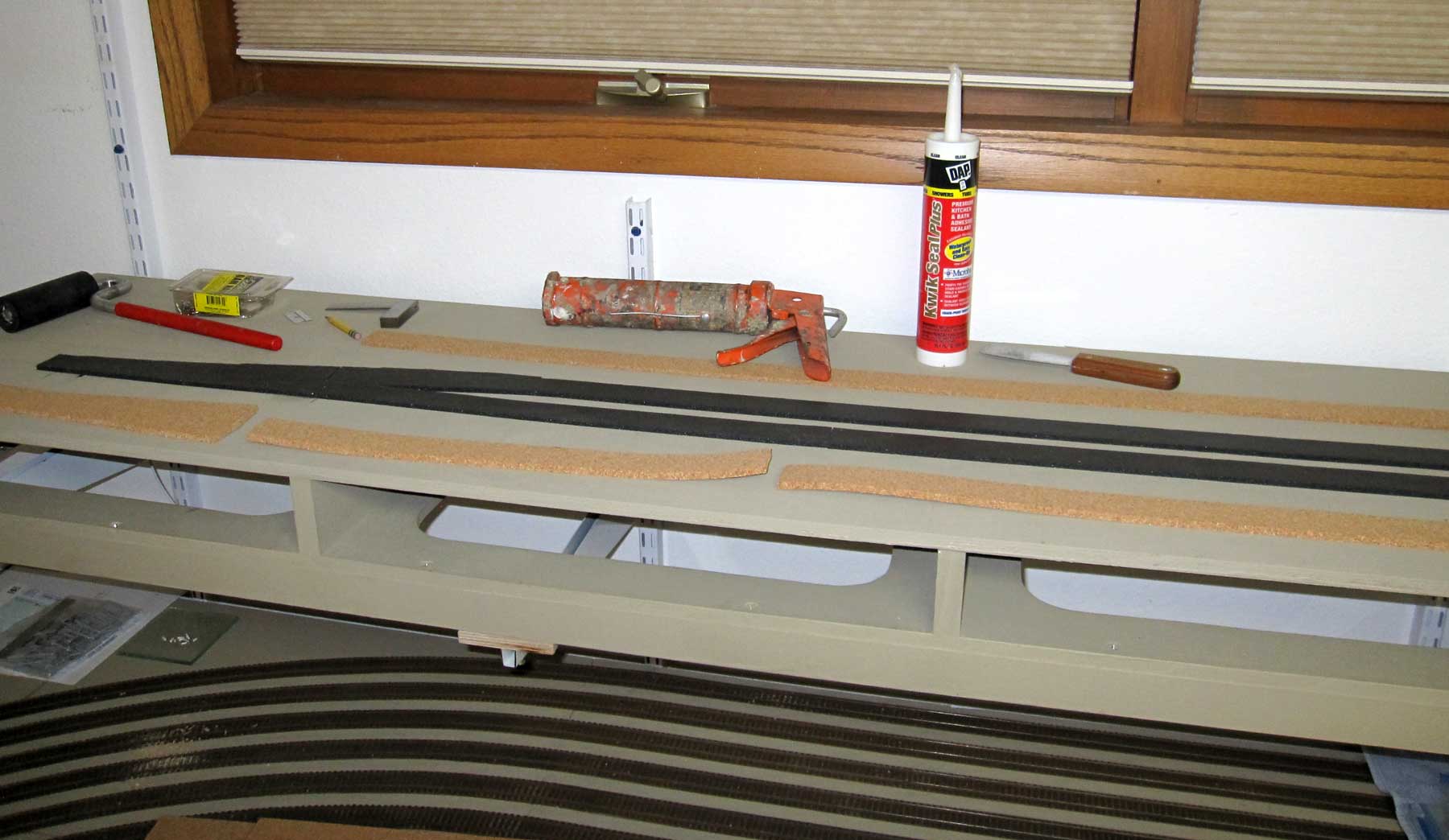
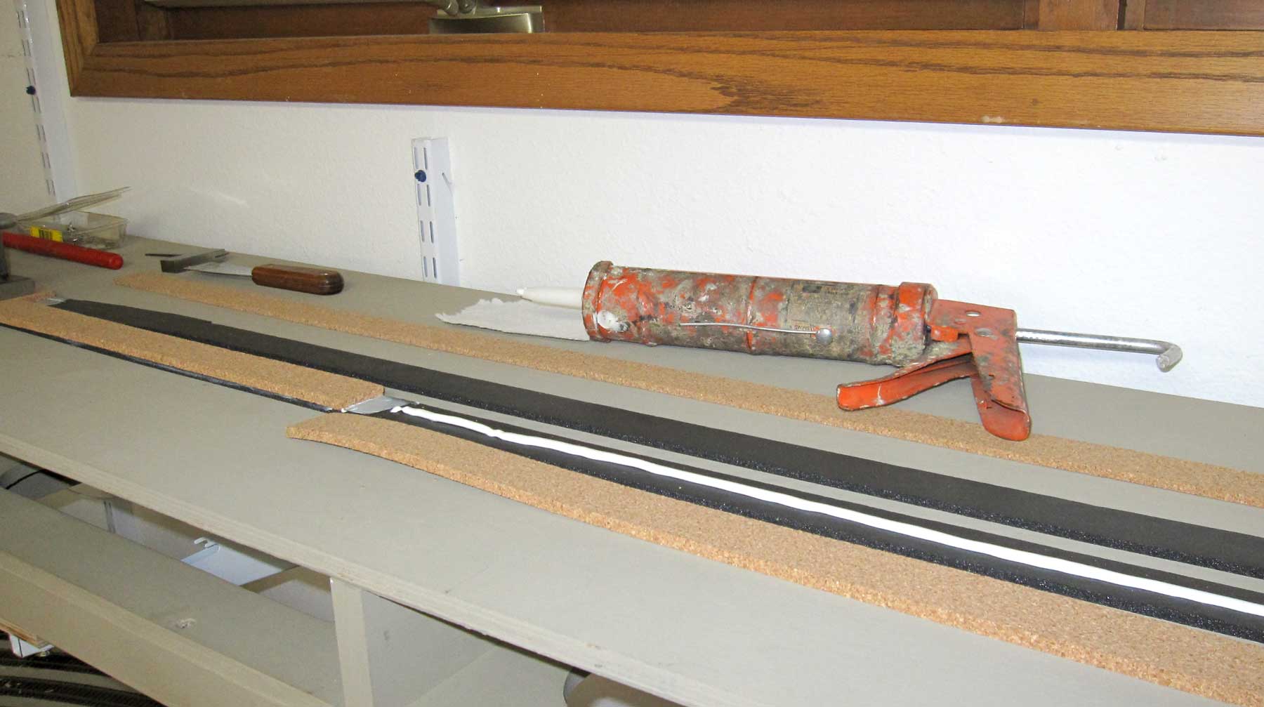
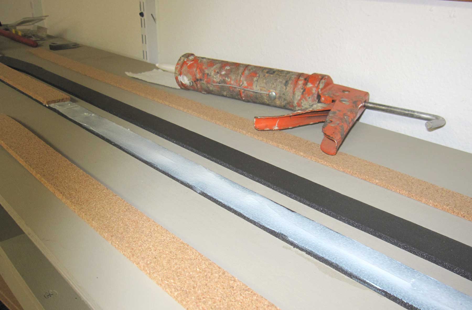
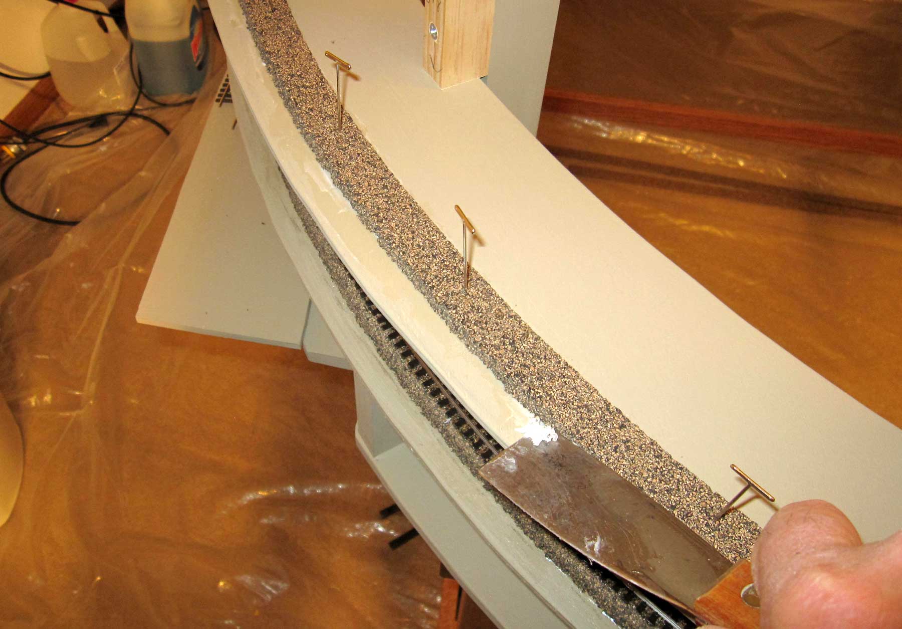
I used DAP Kitchen and Bath Adhesive for gluing down the cork and track. The adhesive was applied as a bead along the center of the foam tape, spread with a putty knife, and the cork was applied in two sections along the track centerline for curves and as one piece for straight track. When the adhesive had dried, the track was glued to the cork in the same manner. I used T-pins to hold the cork and track in position, and weights to insure that it didn’t move until the adhesive was dry. Excess adhesive can be removed with a putty knife.
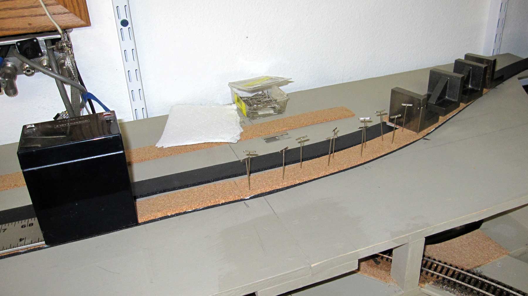
For parallel track sections in yards, I found my book collection to be invaluable as track weights. I covered the track with waxed paper strips then piled the books onto the track to hold it down until the adhesive had set.

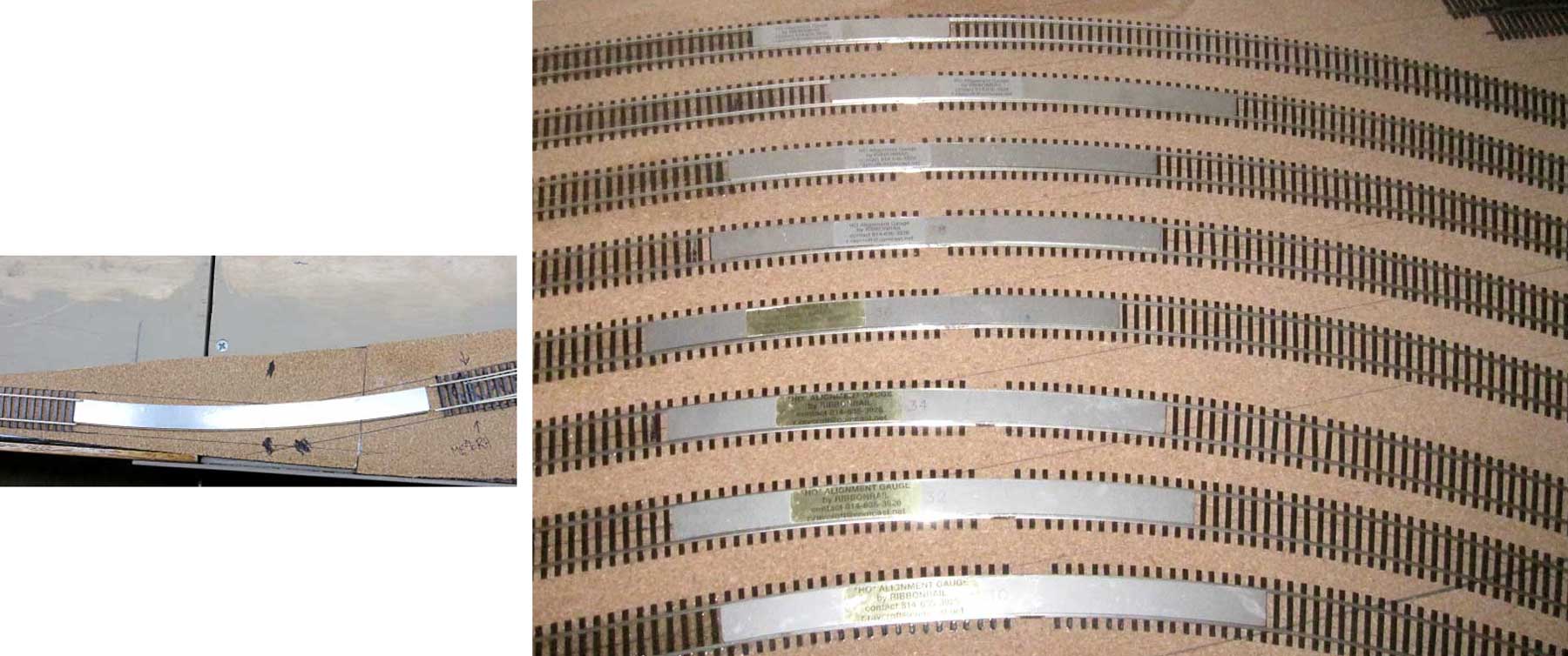
I used Ribbon Rail curve templates to form curves in flextrack. Micro Engineering has a reputation for being stiff, but I had no trouble forming curves using the templates. I pre-formed all flextrack curves before gluing them down to minimize flexing while gluing the track onto the roadbed and pinning it down.
I soldered all rail joints. The ambient temperature of the layout room varies from 65 degrees in winter to 78 degrees in summer, so I’ll watch for buckling and cut gaps as required. Track feeders are ‘spike head’ style, which are almost invisible after the track is painted. To make spike head feeders, I cut four inch lengths of AWG 22 solid copper wire, strip 1.25 inches of insulation, flatten the end of the wire with flat jaw pliers, and trim the end and sides with flush cutting nippers. I also strip about an eighth inch of insulation from the other end of the feeder wire to provide a contact for later testing. I use red wire for the hot wire and black wire for common. I drill holes through the ties, roadbed, and sub-roadbed adjacent to the rail with a #62 bit, then insert the feeder from the bottom and bend the wire slightly so it remains in place. Then I bend the top end of the feeder 90 degrees to form the spike head. I lightly tin both the rail connection and the spike head feeder, then position the feeder on the rail and touch it with the tip of my soldering iron. For rail soldering, I set my soldering station at maximum power so that it instantly heats the rail, vaporizes any oils, melts the solder, and makes the joint in less than 3 seconds. This process minimizes cold solder joints and tie melting. I test the integrity of the solder joint by attaching the leads of my multi-meter to the track and the free end of the feeder wire and checking continuity on the ohmmeter setting. You want to see zero ohms.

I use switch motors on all of my turnouts because I don’t want operators reaching in to operate hand throws. I’ve seen the damage that occurs when ham-handed operators fumble with hand throws, so I’ll practice prevention. Because I run short wheelbase locomotives and a trackmobile over #8 frogs, I have to power my frogs. I solder a six inch length of green insulated AWG 22 wire to bottom of the frog before the turnout is glued in place.
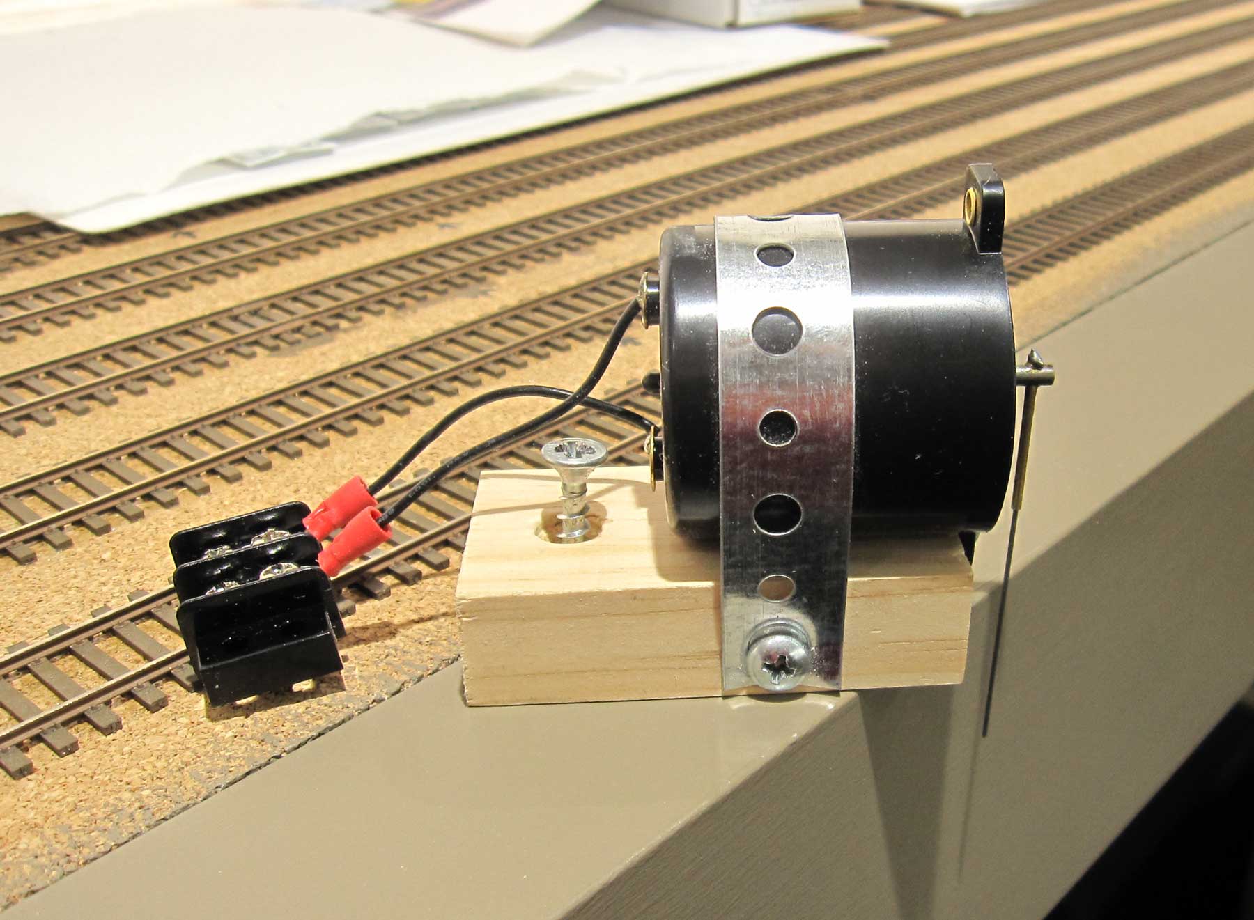
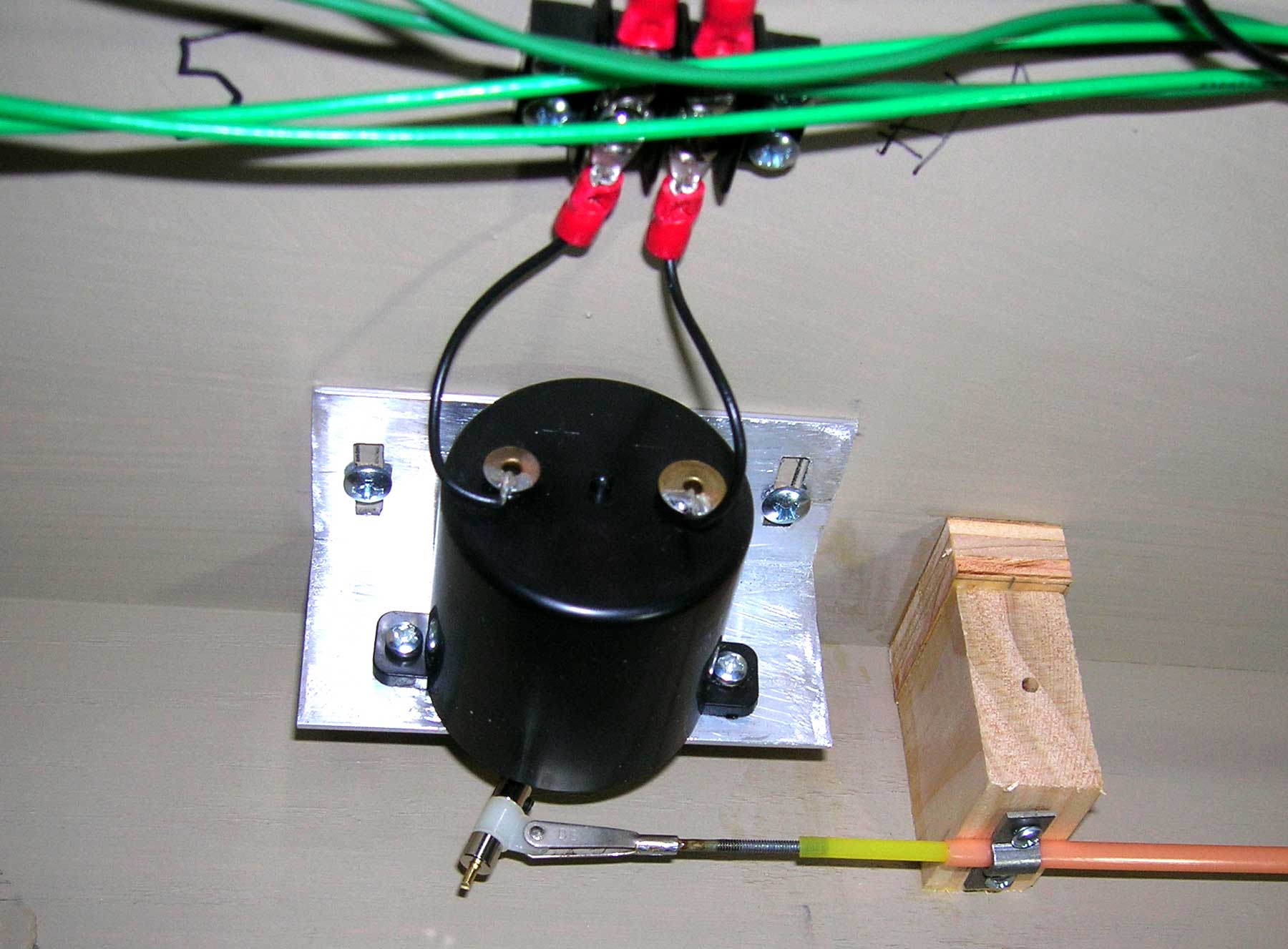
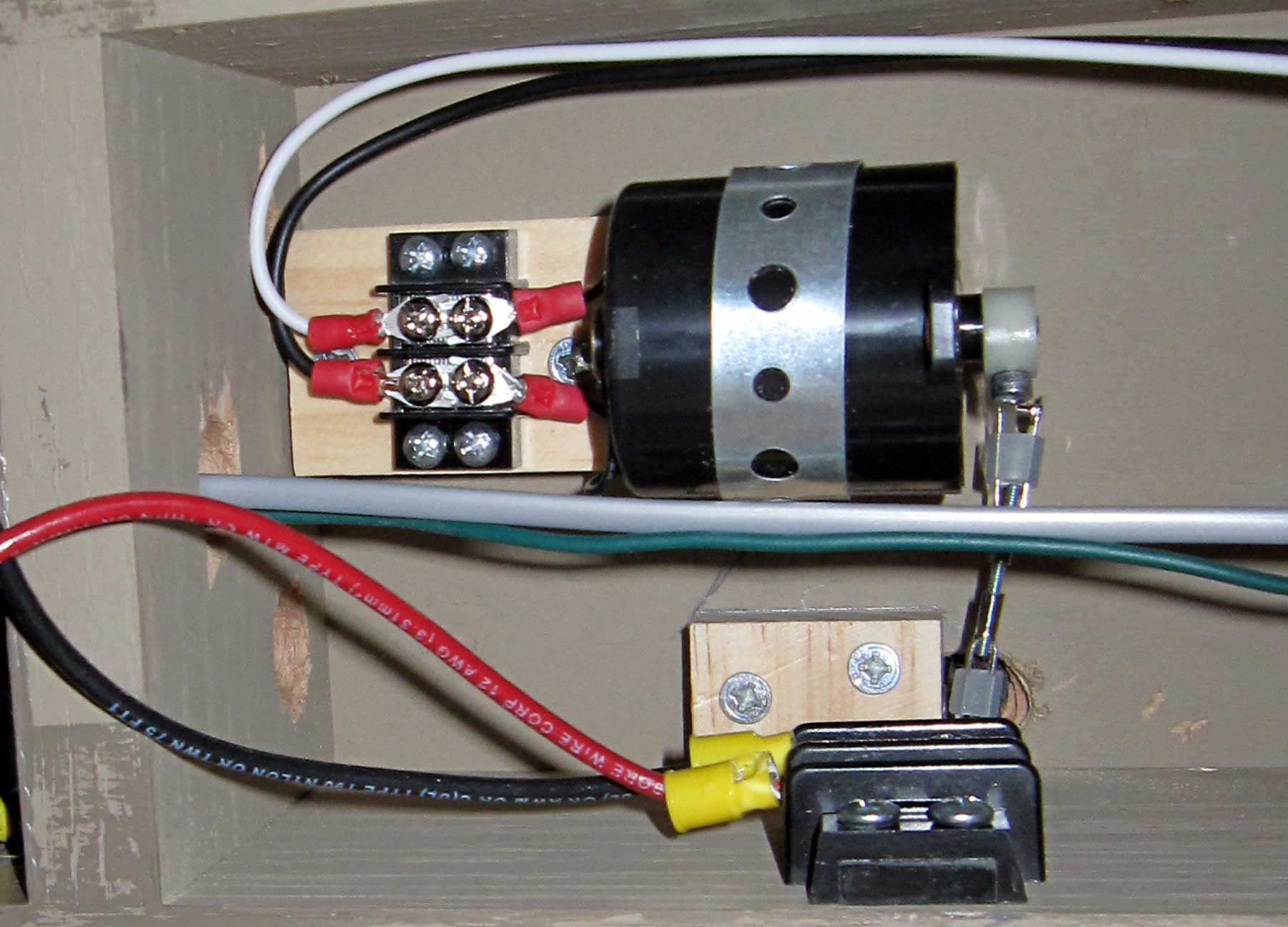
I use SwitchMaster motors. To mount them horizontally, it is necessary to make a mounting bracket. I use two styles of mounting fixtures. The first one is made from 1/8 x 1 ½ x 1 ½ inch aluminum angle. The motors shown below will be covered by an express building.

The other style is made from a short piece of 1 x 2 pine. This style is narrow enough to mount close to the side of the grid.
Occasionally, a throw bar is a location that prevents using normal motor mounting techniques, such as above the duckunder. As fate would have it, I needed to mount a motor above the large shelf bracket supporting Chicago. To do that required a remote linkage made using radio control model airplane components.
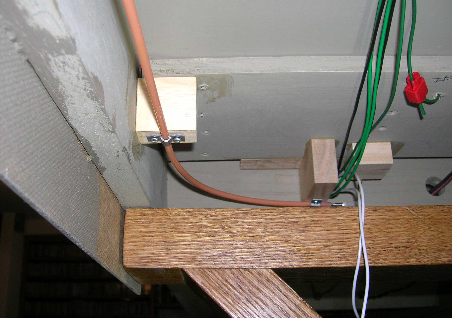
The most difficult motor mounting situation occurred under the narrow support for the fireplace lift-out. The throw bar hole was so close to the edge of the grid that I had to mill out wood to make enough room for the remote linkage to pivot.
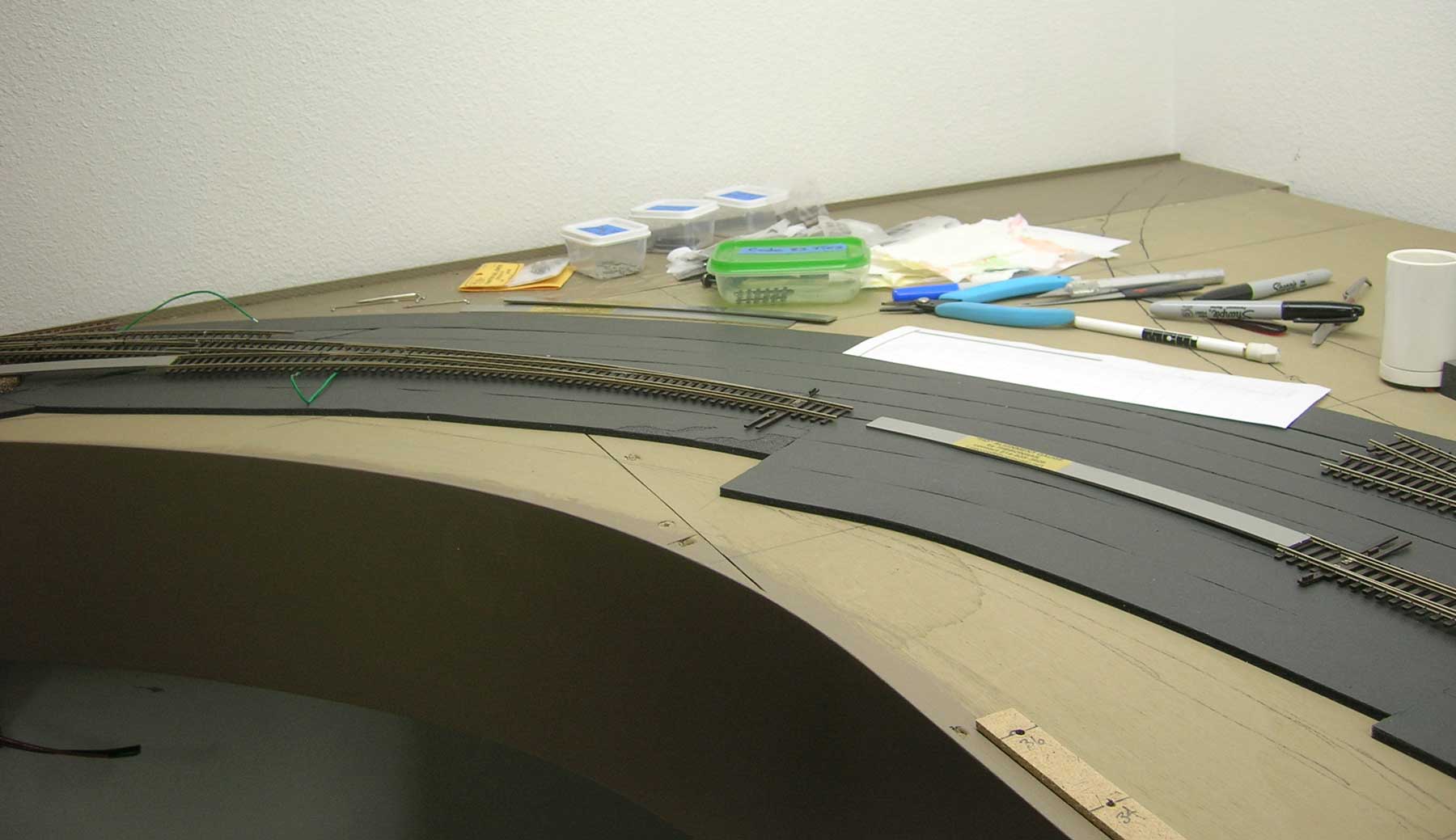
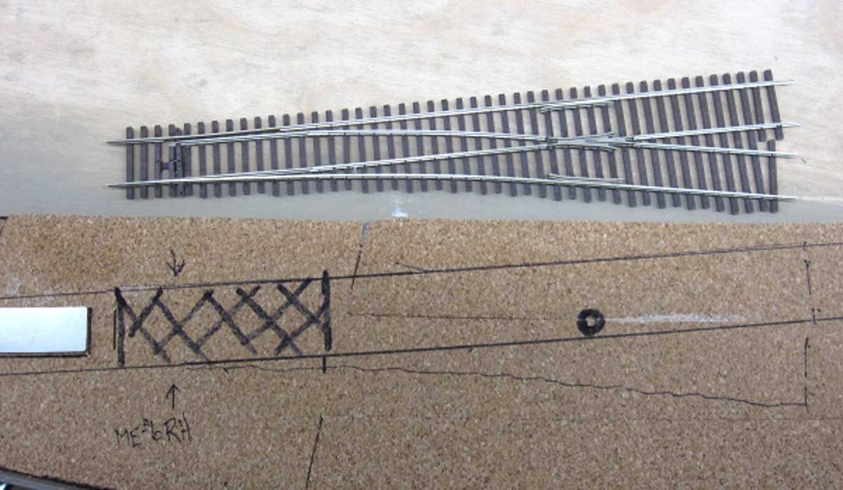
When laying turnouts, I use a black felt tip pen to mark the cork roadbed where the frog wire hole penetrates the roadbed, and where the throwbar actuator wire is located. I crosshatch the area under the points so that I can avoid applying adhesive to those areas when I glue down the track. The throwbar actuator wire hole and the frog power wire hole must be drilled before gluing down the turnout. Don’t ask me how I know that.
Walthers-Shinohara turnouts have to be cut back to achieve two-inch track centers. This is largely a cut and fit proposition.

Micro Engineering turnouts are sized to accommodate two-inch track centers, simplifying track laying. For crossovers, I spliced both Walthers-Shinohara and Micro Engineering turnouts. For Walthers-Shinohara turnouts, this process involves cutting rail and ties so that the turnouts fit together on two-inch centers. The process is easier for Micro Engineering turnouts. It involves pulling the frog rail from one turnout, cutting back the ties of the second turnout, and sliding the frog rail of the second turnout under the molded spike heads of the first turnout. It’s easier to do than describe. The splice avoids the need for a rail joiner to connect frog rails because with a splice, there is one continuous piece of rail to the frog.

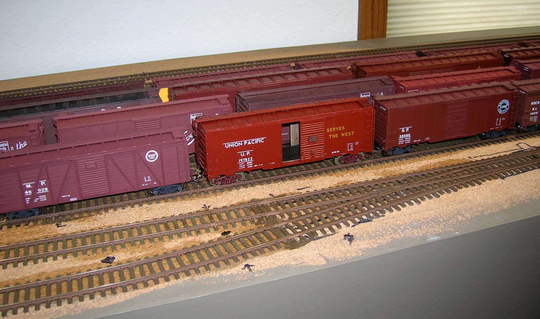
I paint my track. The first step is to airbrush the track and ties with the desired tie color. After the ties are dry, I hand paint the sides of the rail that are visible from the aisle according to usage and age. Mainline rail is darker with less rust, while yard tracks and spurs become progressively rustier and ties become more and more weathered.
Here’s a view of Chicago yard with painted track. I’ve chosen not to super-detail track. While I like the appearance, I believe that my time would be better spent doing other things for the railroad, after all I’m now 74, and the clock is ticking.
Next time I’ll talk about wiring and control systems for the railroad.
We will continue with Nelson’s progress in upcoming blog posts. Questions and comments can be posted below. Please follow the instructions so your comment can be posted. All comments are reviewed and approved before they appear. To subscribe to this blog, enter your info for a comment and check the last box to notify of new posts by email. Share the blog link with other model railroaders.
The spike-head feeder didn’t originate with me. Read the September 2006 Model Railroader page 48. There was an earlier description of these feeders, but I don’t remember the reference. It was also in the 8-2009 book titled How to Build Realistic Reliable Track, page 43.
Nice work. In 60 years of hand laying track
your method of feeding the rail through the tie as if a spike is brilliant. Congratulations to you or who ever thought of it.
One comment. Humidity is more the enemy than temperature variation.
John Rogers
Butte Montana
After our house fire in 2013 Service Master brought in a big dehumidifier to dry out the basement. It did such a good job the lumber in my RR shrank and threw the track out of alignment. So, yes, humidity is a bigger factor than temperature.
Great “spike” wire connectors!
I ordered the camper tape through Amazon.com. The brand I use is called Topper Tape, and get it from http://www.truckoutfittersplus.com/store/topper_parts_tapes_and_seal.html
or
http://apiclamps.com/access.html
whichever has the best price. There are several widths. It’s 3/16 in. thick, just like Midwest cork roadbed. I used 1.5 in. for the yard and 1.25 in. for everything else. Widths greater than 1.25 in. won’t take curves in HO scale. My minimum radius is 28 in. You can split it down the middle and apply it in two strips for tighter curves. It’s self-adhesive on one side, with a stiff paper backing on the other side. You can lay straight sections with the paper backing attached to the top, but you have to remove the backing about 3 ft. at a time to lay curves. I work right off of the roll, otherwise you’ll have a tangled sticky mess. The finished track is slightly springy, i.e. it depresses slightly if you press down hard, but my ABBA sets don’t cause it to flex. I did not use camper tape on the staging yards or liftouts, or helix. Chuck Hitchcock wrote an article in the August 2003 Model Railroader on this track laying method.
Thank you!
Nelson, where did you find the foam tape? Thanks
Nelson your track work is looking good. I especially like the spike head track feeders.
Nice work. I really like your technique for soldering feeder wires to the rail.
Very nice.