Nelson Moyer returns with another installment on his layout developments.
My inaugural post provided a capsule history of how I arrived at the decision to build a model railroad, and it described the evolution of the track plan. While the track plan captured my dream with surprising fidelity to the prototype, I have only 312 square feet to model a mile long yard in Burlington and the 53 mile branch line to Washington. The full realization of what this would entail hit me when I counted the number of rooms that the railroad must occupy, and the engineering marvels that would be required to make it happen. It’s easy to draw your ideal track plan, but quite another thing to actually design and build the benchwork. This month, we’ll look at overcoming some of the impediments my house presented to the fulfillment of my dream. Sometimes you just have to play the hand you’re dealt.
My house is the split foyer type that was popular in the Midwest during the 1970s. Most of the living space is on the first floor, and the basement is half living space and half two car garage. My basement living space has a family room, bedroom/home office/layout room (henceforth referred to as the layout room), laundry room (more like a laundry closet), a utility closet, and the downstairs bathroom with a shower. When I started designing the layout, it was to be confined to the layout room, which provided 208 square feet of space. The final plan was much more expansive in scope, but would consume only 312 square feet of floor space by use of liftouts through the laundry room and bathroom, and by preserving the living space in the family to the greatest extent possible.
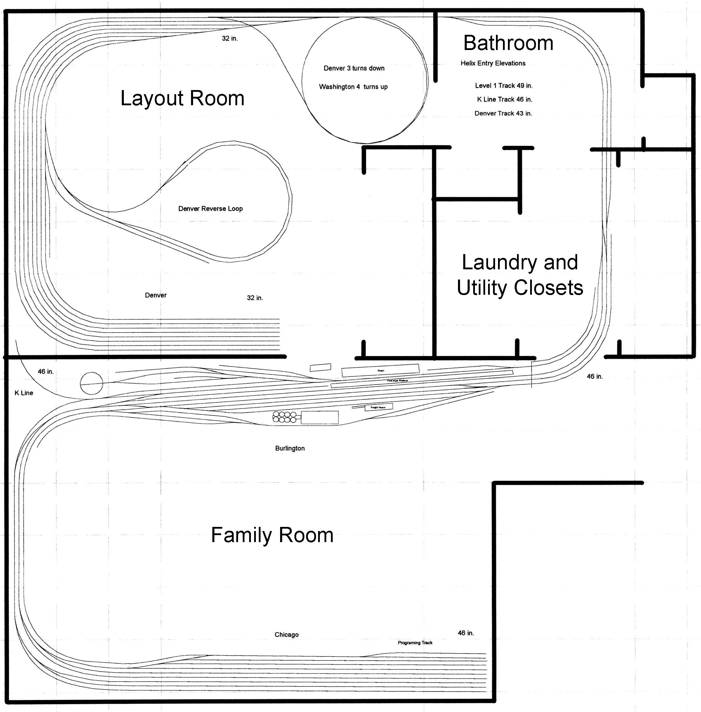
The plan created several obstacles for operators, but I felt that they were unavoidable if I was going to be faithful to the prototype. The two most loathsome impediments are two long duckunders (18 and 56 inches long and both are 45 inches high) and two aisle pinch points 19 inches wide. As with most basement layouts, there are stairs.
The plan also created several obstacles for the builder. The basement family room has a picture window that is 110 inches wide, and ideally, that span would be unsupported between the ends.
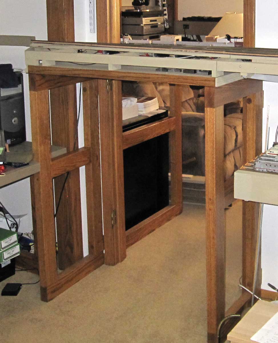
This room also has a fireplace, and the span across the front of the fireplace must lift out. The television will have to go upstairs, but I haven’t given up on a projection TV system with a drop down screen in front of the fireplace.

The multi-track curved section leaving Burlington Westward is both a duckunder during operation and a liftout the rest of the time. The straight section across the utility room must support the curved duckunder/liftout, yet be removable for access to the furnace, hot water heater, and water softener.

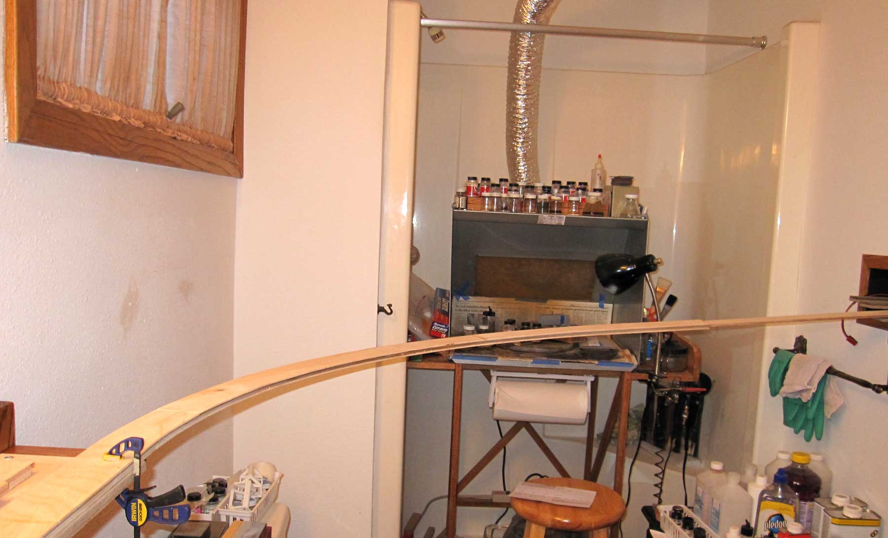
The curved bathroom section must be a liftout to access the toilet and shower because my paint booth is in the shower (see NMRA Magazine April 2011 pp. 26-27).
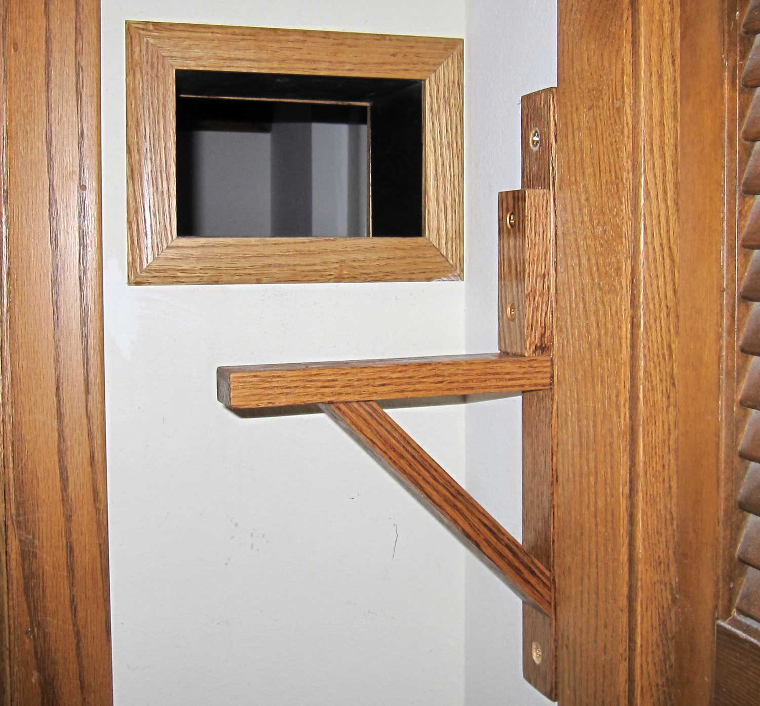
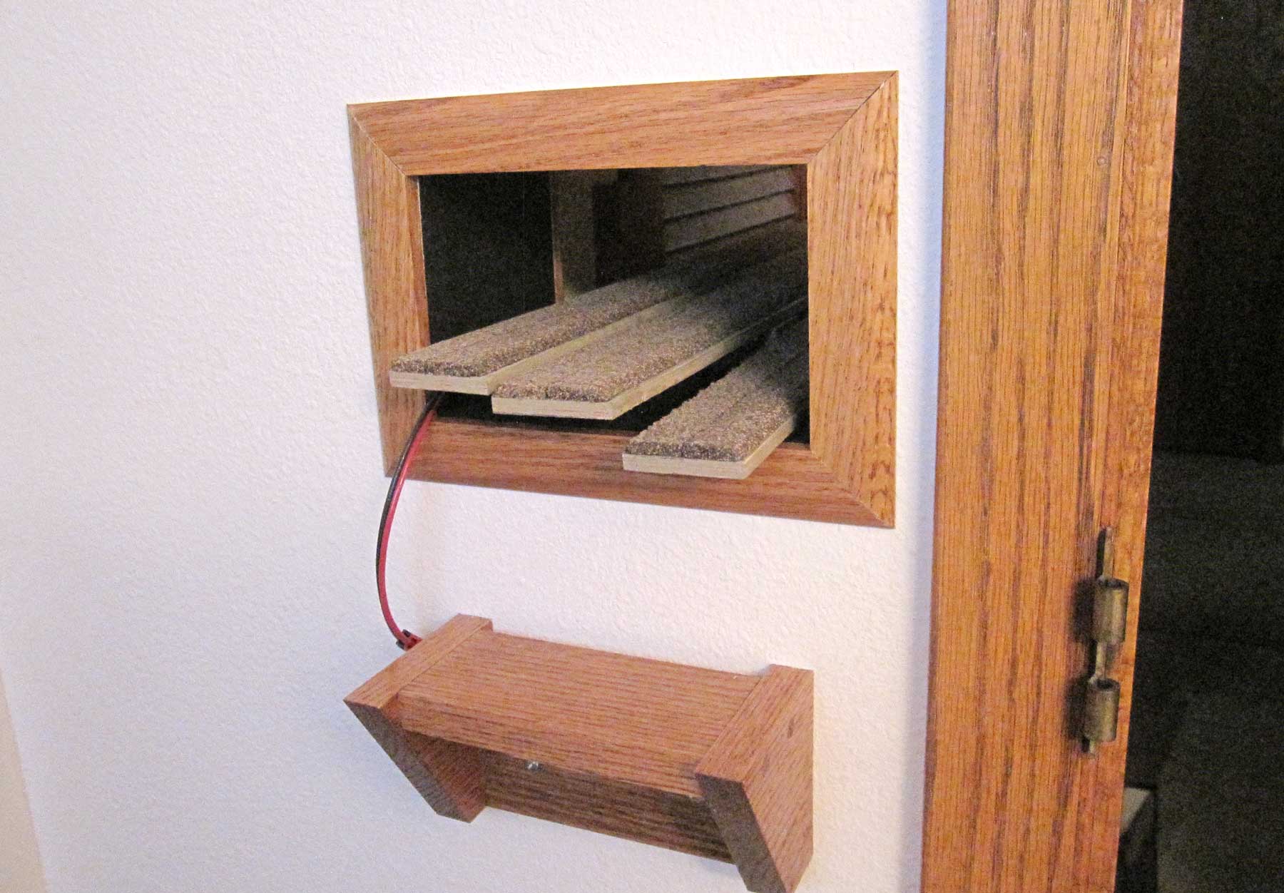
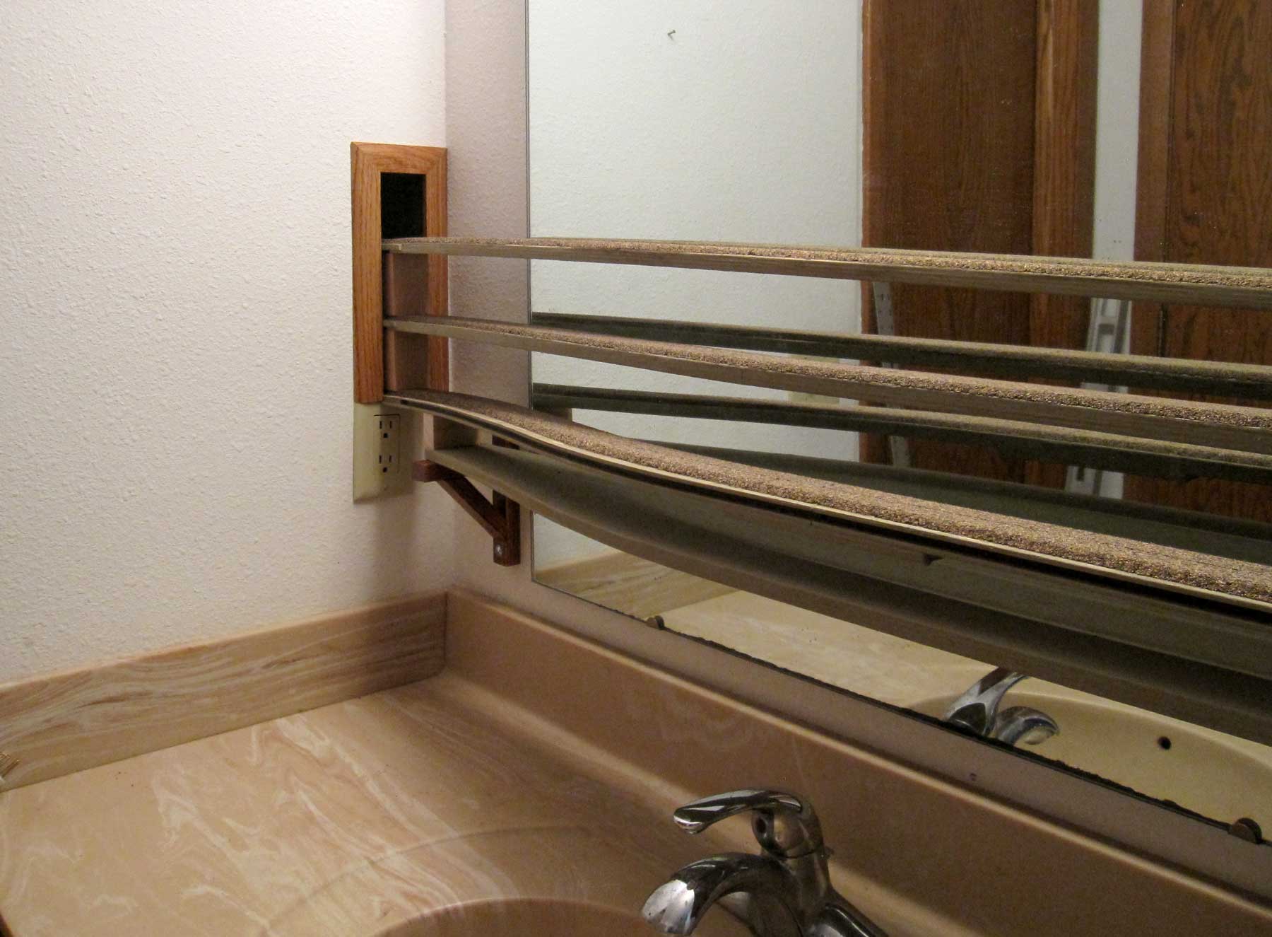
Three horizontal tracks penetrate the laundry room wall, emerging in the bathroom where they must change elevation plus or minus three inches and penetrate the other side of the bathroom wall as three vertical tracks with elevations of 43, 46, and 49 inches.
This engineering marvel is necessitated by the fact that the helix entries are on the other side of the bathroom wall, and the kitchen water pipes provide a scant 2.75 inch clearance for the roadbed through the wall space.
The helix presented its own set of problems. To maximize space for branch line towns, it was necessary to place the helix in the corner alcove at the door between the layout room and the bathroom. This permanently blocked the doorway, so I removed the door knob and installed a brass plate over the hole to insure privacy. The width of the alcove is 61 inches, so that dimension became the limiting factor for the helix radius. I ran overhang tests on 85 foot passenger cars, and determined that 29 inches was the maximum radius I could use for the helix, and this radius would only be possible if I cantilevered the sub-roadbed turns from a central support. I’ll describe the helix in a future post.
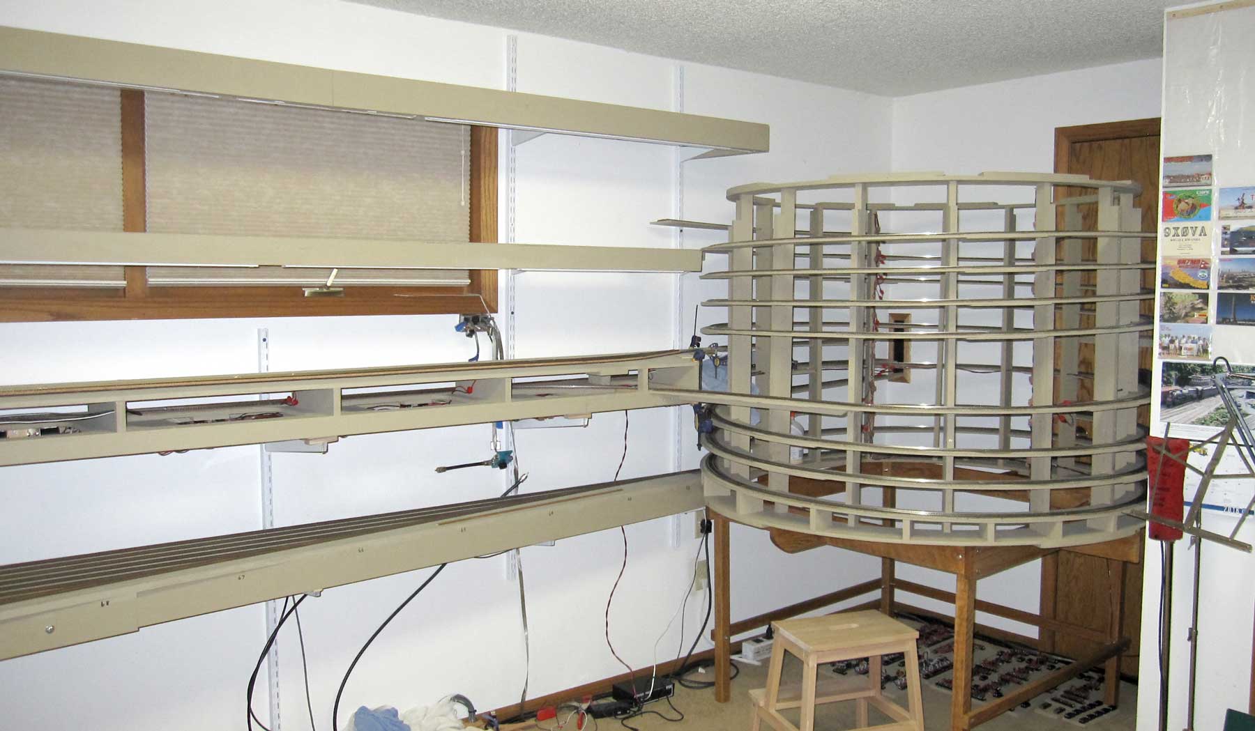
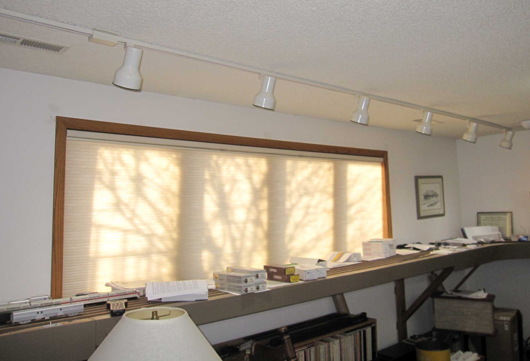
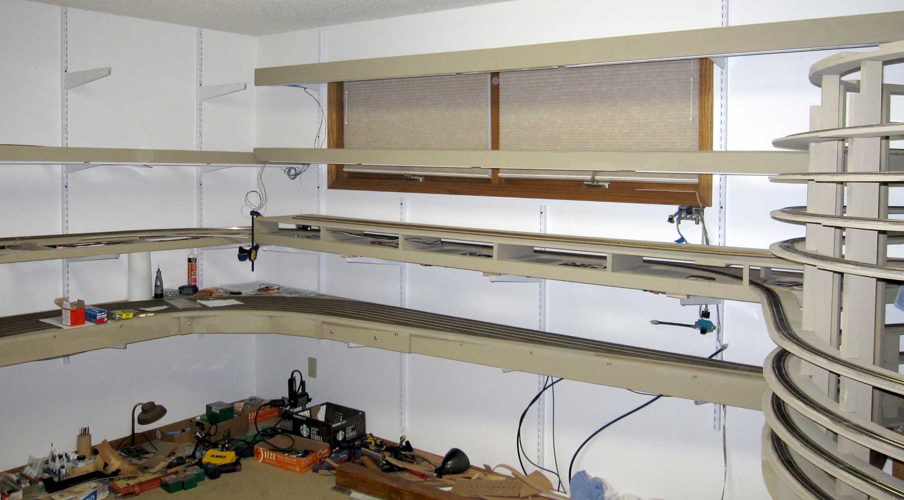
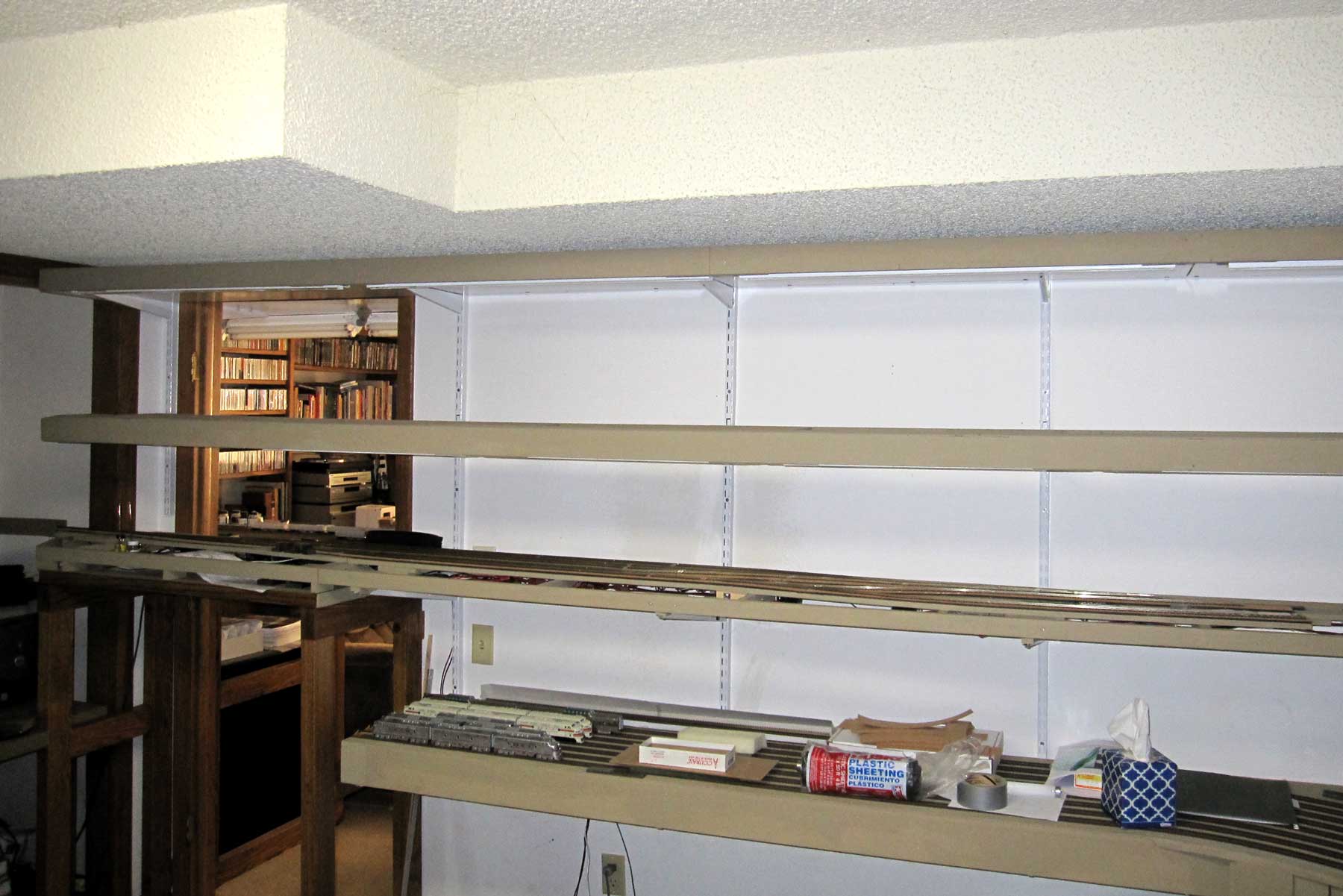
The layout room has two windows, a long high double window along the North wall, and a large window well window on the West wall. Both windows will be blocked by the backdrop, so they must be sealed for temperature control and covered to block sunlight.
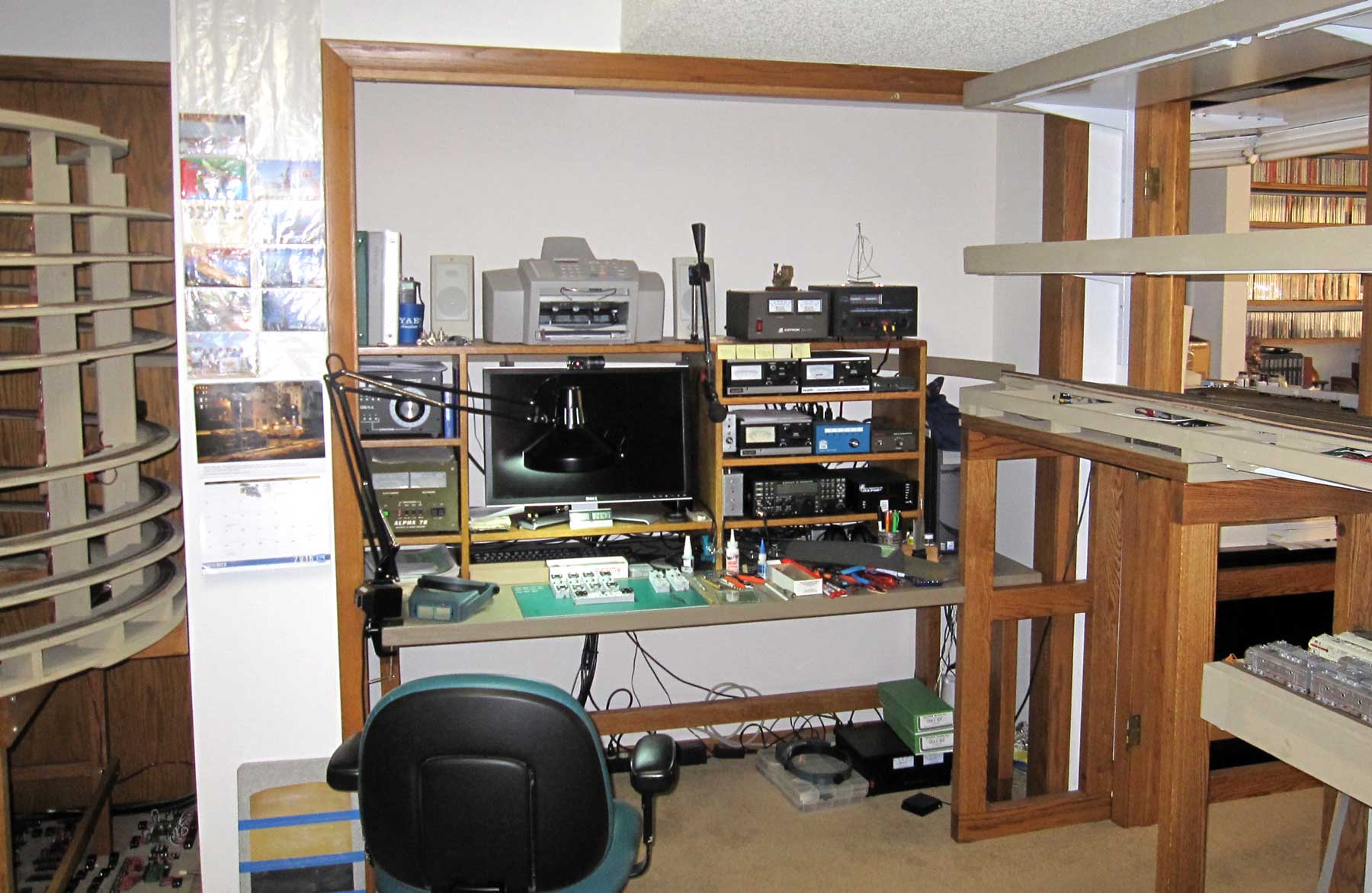
Level 1 passes through the layout room closet and through the closet wall to the helix to get to level two. The line passes through the closet again, on level 2, to get to Washington. The closet also houses my workbench and ham station.
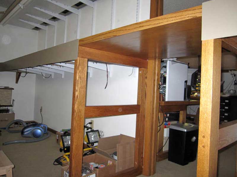
I wanted to shelf mount all of the benchwork for a floating look, but I needed to support three levels at the peninsula. I decided to use a single 4 x 4 post near the center of the reverse loop on the bottom level to support all three levels of the peninsula. The base of the peninsulas would be bolted to the grids along the wall. The rest of the layout and lighting grids would be supported by shelf brackets.

The HVAC plenum runs lengthwise down the middle of the house, and it happens to be located along the wall and across the doorway of the layout room’s South wall. The plenum lowers the ceiling by 10 inches for a full 34 to 54 inches from the wall, thus determining permissible deck spacing at that location, and ultimately determining all elevations on the railroad.
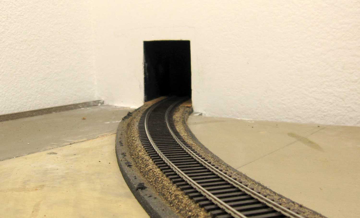
The track plan required five wall penetrations, but only one of them occurred on a part of the railroad with structures and scenery. I made open ended boxes out of quartet inch plywood the length of the wall space, painted the inside flat black, used construction adhesive to secure them in place, then framed the holes with oak molding to match the woodwork trim in the rooms. The hole where the K Line passes through the wall is on an angle, so I made the box longer than necessary then cut the angles on both ends with my miter saw. The opening was made as small as possible possible because this hole is on the part of the layout with structures and scenery. The wall was repaired so that the only evidence of the hole is the flat black paint through the wall space. I’ll use a structure and trees to hide the opening.
Playing the Hand You’re Dealt
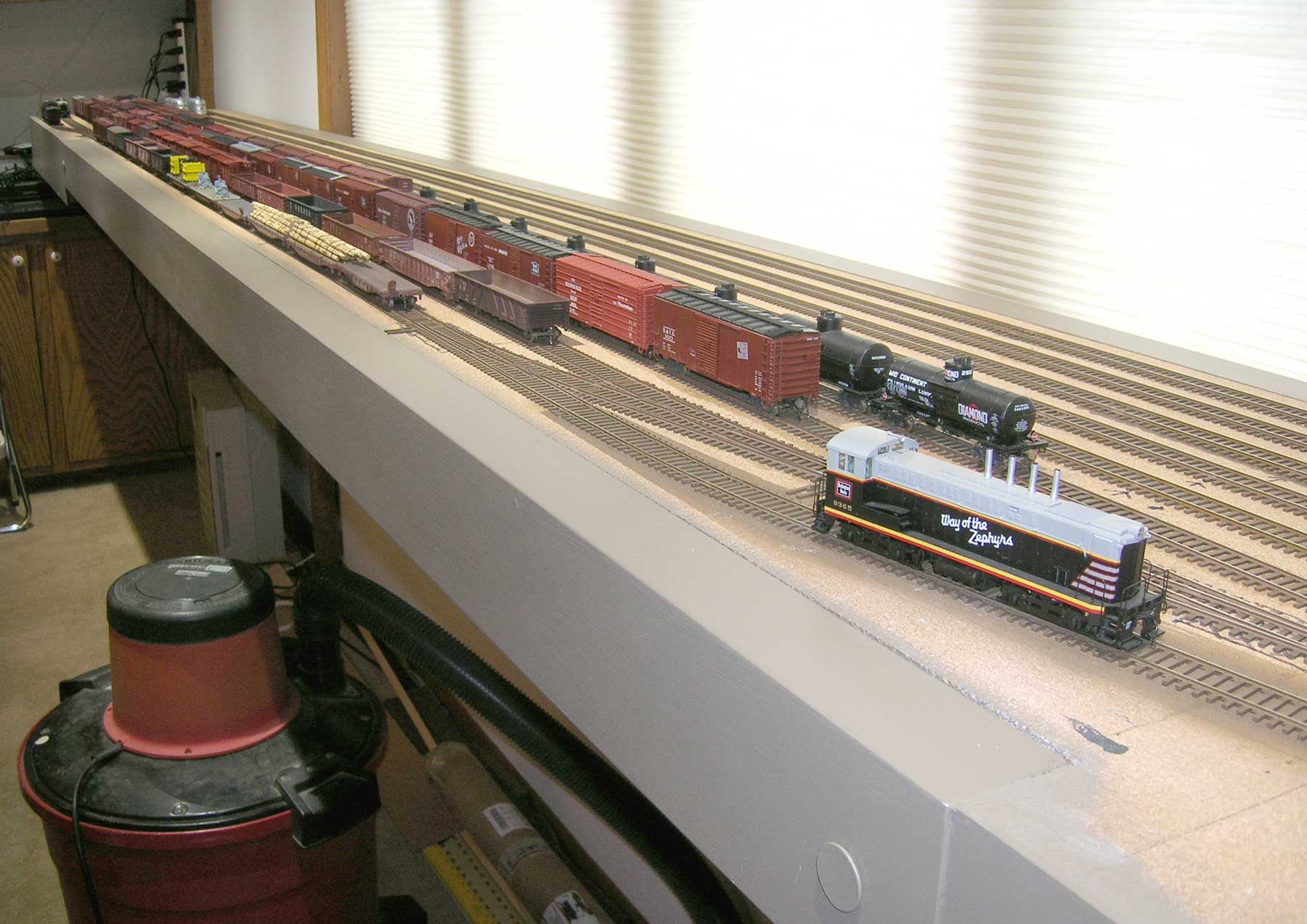
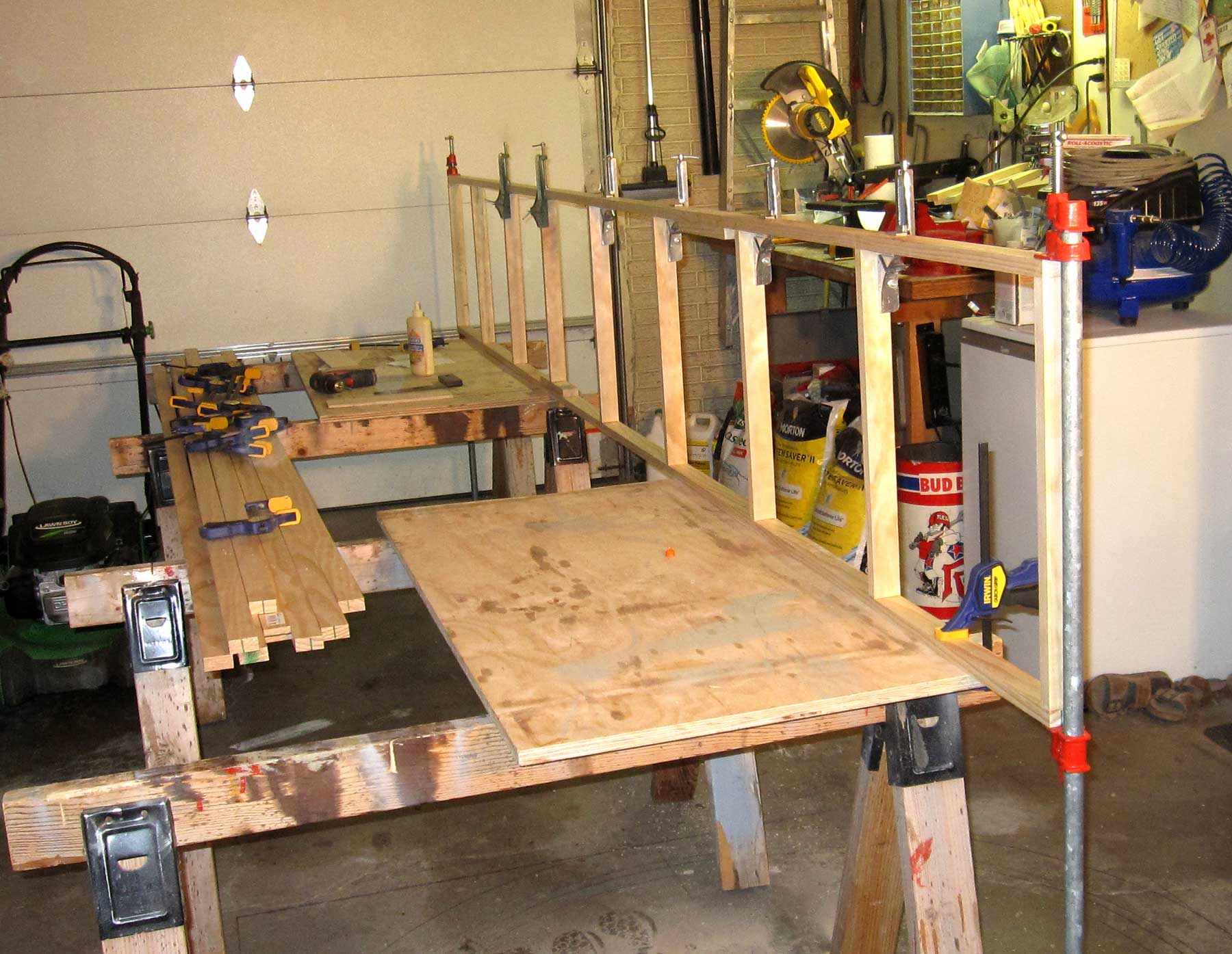
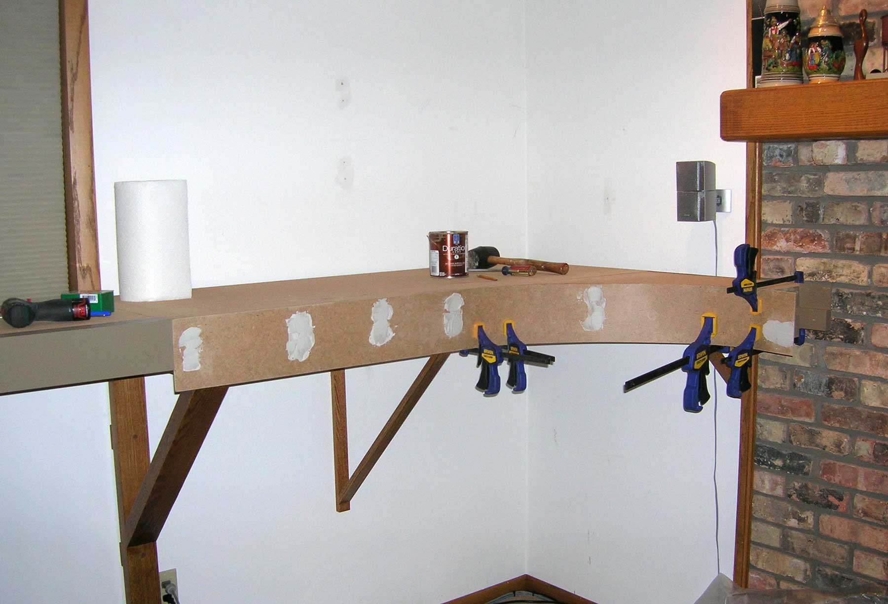
The family room window span was worrisome because it would have to support most of the Chicago staging yard, which includes eight 18 foot long tracks full of locomotives and cars. I wanted to support the span on wall brackets on either side of the 110 inch window without intermediate brackets. I calculated the maximum weight that could be expected in the yard, and performed deflection calculations to determine how best to reinforce the span so that it would not sag – ever! These calculations resulted in selection of 1 x 4 oak lumber for the grid, with quarter inch aluminum C-channel reinforcement on both sides of the grid across the span. The C-channel was attached to the face if the grid using elevator bolts at each end. The main pair of wall brackets supporting the Chicago grid were built from 1.75 x 3.25 inch oak, and they were fastened to the poured concrete basement wall using TapCon concrete screws.

The fireplace liftout is a single piece of 1/8 inch thick aluminum 2 x 6 inch tube with 3/16 inch cork roadbed. The narrow grids on both sides were designed to support the liftout, and the fascia holds it in position laterally. Cabinet magnets provide additional stability and provide electrical continuity.
I wanted the tracks above the duckunder to be earthquake proof, because I’ve seen and experienced the effects of raising up too soon while navigating a duckunder. The sub-roadbed for the main duckunder at Burlington and Winfield is made from two pieces of ¾ in. plywood with three wire channels cut with a router before the pieces were laminated together to form one heavy piece of plywood. The front edges were trimmed in oak. This piece was screwed down to the duckunder supports, which were made of 1.75 x 3.25 inch oak. The oak supports also support the grids on either side of the duckunder. The supports were built as separate sections, then bolted together through the wall. Elevator bolts were used as adjustable feet to compensate for irregularities in the basement floor. Note the hand-holds to assist operators navigate the long span.
The curved duckunder/liftout at the end of the Burlington yard was made from one piece of half inch plywood with pieces of quarter inch plywood laminated on each side, forming a wire channel on the outside of the curve. Edge trim is yet to be determined. This liftout is keyed to the space and held in place by magnets.

The straight liftout section in the laundry room has to support the curved liftout with four tracks, and it had to also be removable to access the utility closet. Four switch motors had to be mounted under that liftout, so I build it on a grid of 1 x 4 pine with half inch plywood on top to protect the switch motor linkages and provide space for the associated electronic control boards. The straight liftout section is supported on two oak brackets, and cleats on the end and side of the straight liftout support the curved liftout.
The sub-roadbed through the bathroom was made using a quarter inch plywood core with two pieces of 1/8 inch plywood laminated to each side. Of the three parallel pieces, only the front piece has a wire channel. These three pieces were mounted side by side on a half inch plywood base using risers to set the grades. This liftout is supported by oak brackets on each end, and secured using magnets and spacers to prevent both lateral and vertical movement under normal conditions.
Now that I’ve briefly described the construction techniques for the problem areas of the layout, I’ll describe the overall construction methods I used. The part of the layout that runs along the walls is made up of a series of modular grids built from 1 x 2 or 1 x 4 pine, with half inch plywood sub-roadbed. All grid joints are glued and pegged. The plywood is glued and screwed to the grids. The wall-mounted grids are supported on shelf brackets except at the duckunders, and these modules are bolted together, and screwed to the duckunder supports. The peninsula is a grid of 1 x 2 pine with 1 x 2 joists to support the sub-roadbed profile, attached at the base to the wall grid and supported at the end by a 4 x 4 post. The connecting tracks through the bathroom and closet have laminated sub-roadbed as described above, with wire channels on one edge, and these sections are supported on brackets made from 1 x 2 oak. All oak joints are glued and pegged. Poplar pegs are used with pine and oak pegs are used with oak.
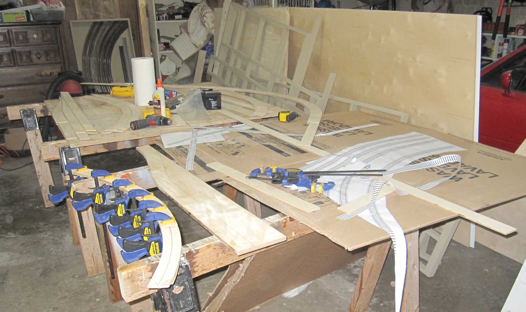
I built the grids in the garage while the weather is comfortable. I bought select pine and Baltic birch plywood at Menards, and hardboard for fascia and the valance at Lowes. The 1/8 inch Baltic birch plywood used for laminates and splice plates came from Woodcraft. I paint all pine and plywood surfaces with Dutch Boy DC647 Hen House Flat latex. The fascia and valance is painted with Sherman Williams Sherwin Williams #7514, Foothills Satin Acrylic Latex. I stain the oak with Minwax Golden Oak before adding two coats of Clear Satin polyurethane.
I wanted the fascia to be as narrow as possible and still hide the switch motors, so it is 5.75 inches high in the family room except across the long window span, where it is the 4 inch height of the C-channel, and across the fireplace, where it is the 2 inch height of the rectangular tube. I chose a fascia color that would not call attention to itself while complimenting the carpet and brick colors in the family room. I didn’t want visible fixtures, so the screws are countersunk.
Because this is my first and only real layout, and I didn’t start construction until age seventy, I’m trying to get everything right the first time. That requires a lot of thought and planning. I created standards for everything, and I document everything. I make computer drawings of everything. I keep a notebook of everything. Want to know a dimension, check the book. Want to know what screw size or wire gauge I used for a particular purpose, check the book. Despite all of the planning and documentation, I admit to an occasional mistake. Usually, it was something I could not foresee due to my lack of experience in model railroading. Fortunately so far, all of the mistakes have been easily reversed. I’ll let you know about some of the more memorable errors in a subsequent post.
Next time, I’ll discuss roadbed and track.
We will feature more of Nelson’s progress in upcoming blog posts. Questions and comments can be posted below. Please follow the instructions so your comment can be posted. All comments are reviewed and approved before they appear. To subscribe to this blog, enter your info for a comment and check the last box to notify of new posts by email. Share the blog link with other model railroaders.
Hi Nelson
two quick thoughts:
1. If there is a will there is a way
2. If you are married, your spouse should be nominated for sainthood.
Cant wait to see more of your layout.
Thank you for sharing
Mark
I have not seen it mentioned anywhere, but would tell tails be of use for the duck unders where someone might come up too soon?
I put the horizontal hand-holds on the duckunder supports as an assist for letting operators know how far down to go and to let operators know when they have reached the end of the duckunder and can rise up. I experimented with the height of the hand-holds to see what was most comfortable for me (I’m 5’9″). I would think tell-tails could be distracting, obscure vision, and be esthetically unacceptable.