A Septuagenarian’s Approach to Layout Wiring
Nelson Moyer is back with an installment on wiring his layout. Click on any image here to review a larger size.
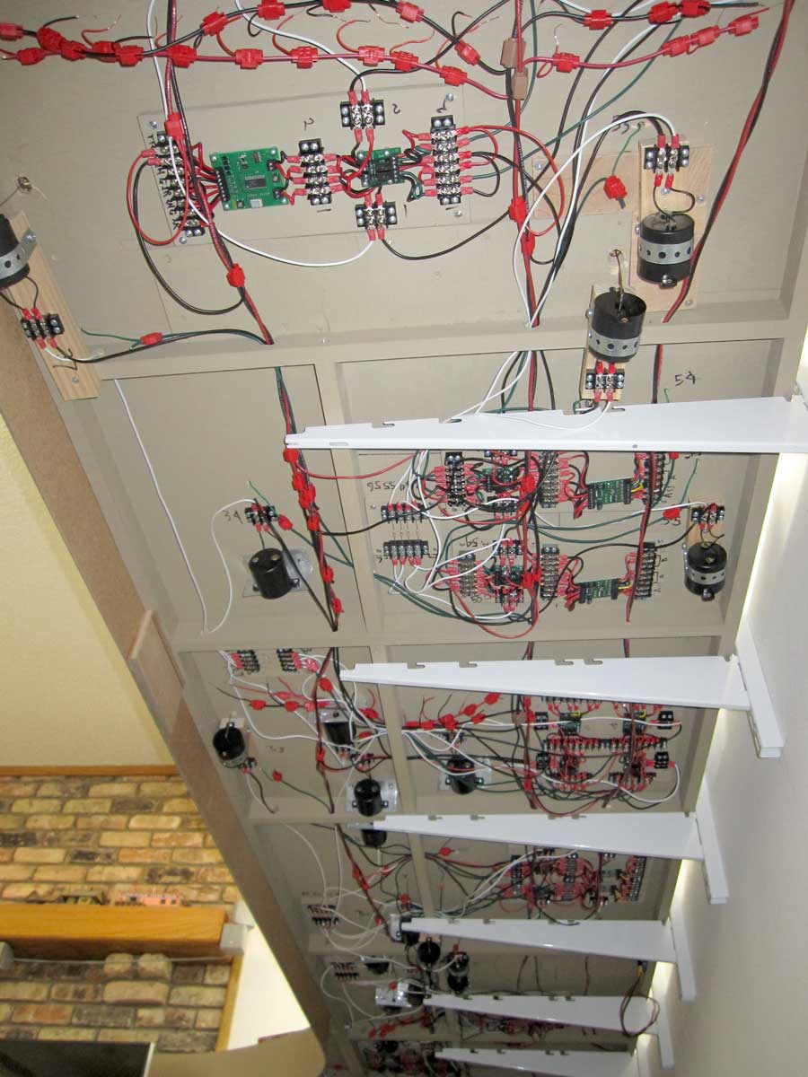
I’m getting old, I wear trifocals, and I have severe astigmatism that is only partially corrected. The most unpleasant thing about building a layout as far as I’m concerned is to have to work under it. I have sought to minimize the amount of wiring I have to do underneath the layout by doing as much as possible at the workbench.
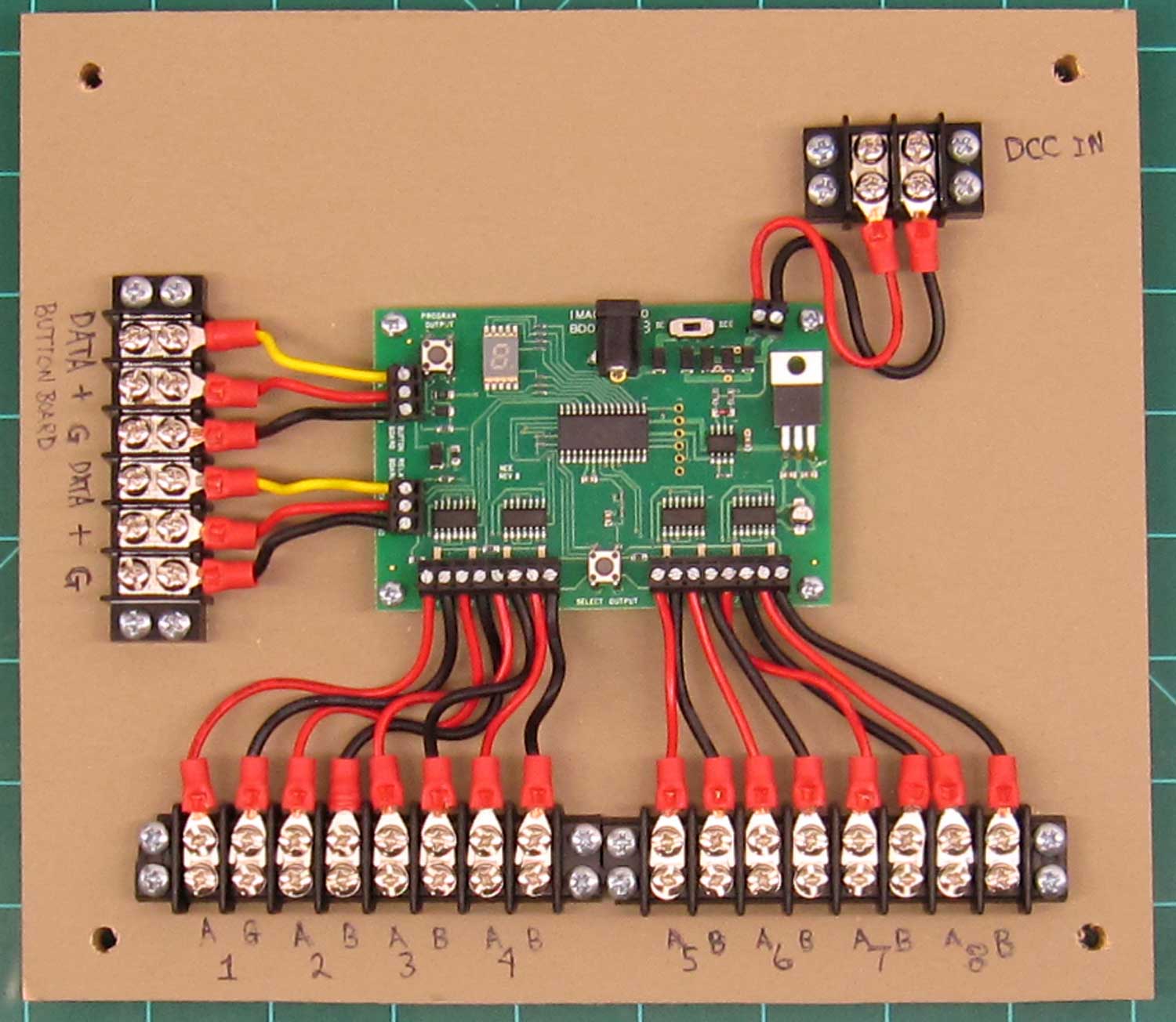
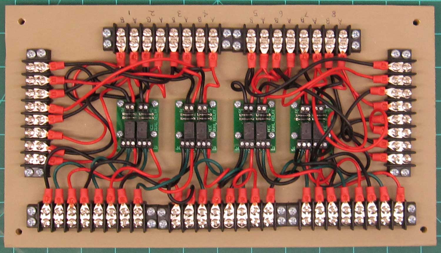
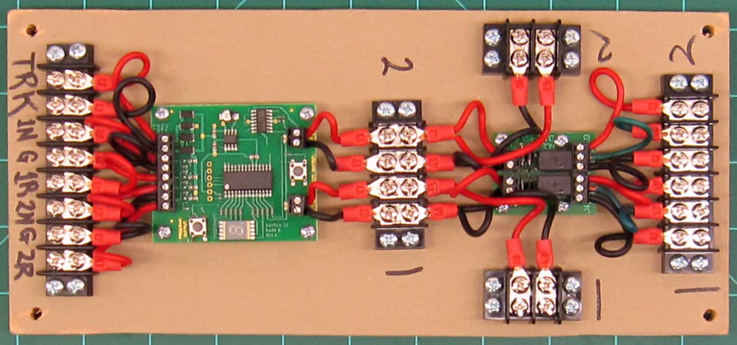
I’m using NCE components for wireless DCC. Besides the command station with 5 Watt booster, I have three additional 5 Watt boosters, two Switch8 boards, eight circuit breakers, a lot of SwitchIt boards, and a lot of Dual Relay boards. Besides that, I have a Mini-Panel and a Button Board for control panel controls (as yet unbuilt). I also have four PSX auto reverser boards. All of those boards are mounted on pieces of half-inch plywood together with the requisite number of terminal blocks so that most of the component wiring can be done at the workbench.
My basement is carpeted, so I decided there would be no soldering under the layout – ever! This meant using insulation displacement connectors (suitcase connectors) and screw type terminal strips for all wire connections. I use the old fashioned barrier terminal blocks because I can see the screw heads better than those on the new mini-terminal blocks.
I wanted to retain switch motor control during a short, so I separated the DCC bus through two circuit breakers for each power district. One side is the track bus and the other side is the accessory bus. While wiring is incomplete at present, I have four power districts, one each for Chicago, Burlington, Denver, and the helix and branch line. The auto reversers control the two reverse loops, the turntable, and the Washington wye.
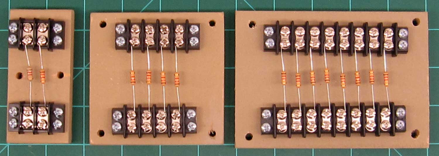
SwitchMaster motors require a dropping resistor rated at ± 1,000 Ω. Because of the different mounting arrangements for my switch linkages, the resistor values vary between 820 and 1,200 Ω. To make swapping resistors easy, I made resistor boards. Resistors can be swapped by unscrewing two screws, removing a resistor, replacing a resistor, and tightening two screws.
The following photographs show the various board designs.
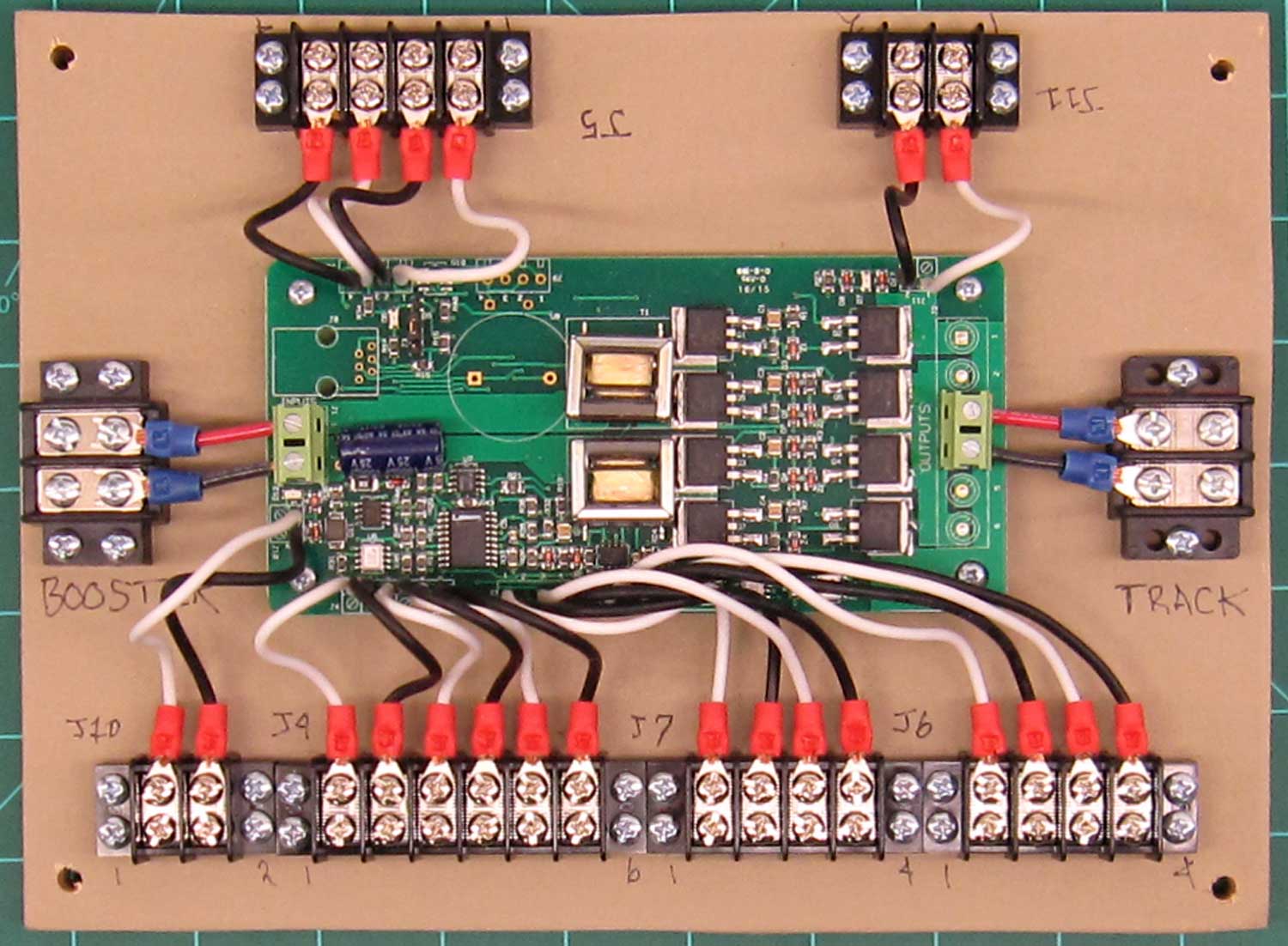

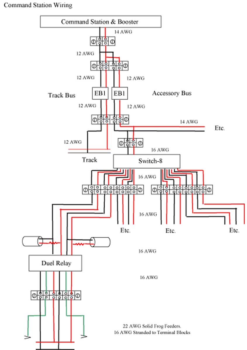
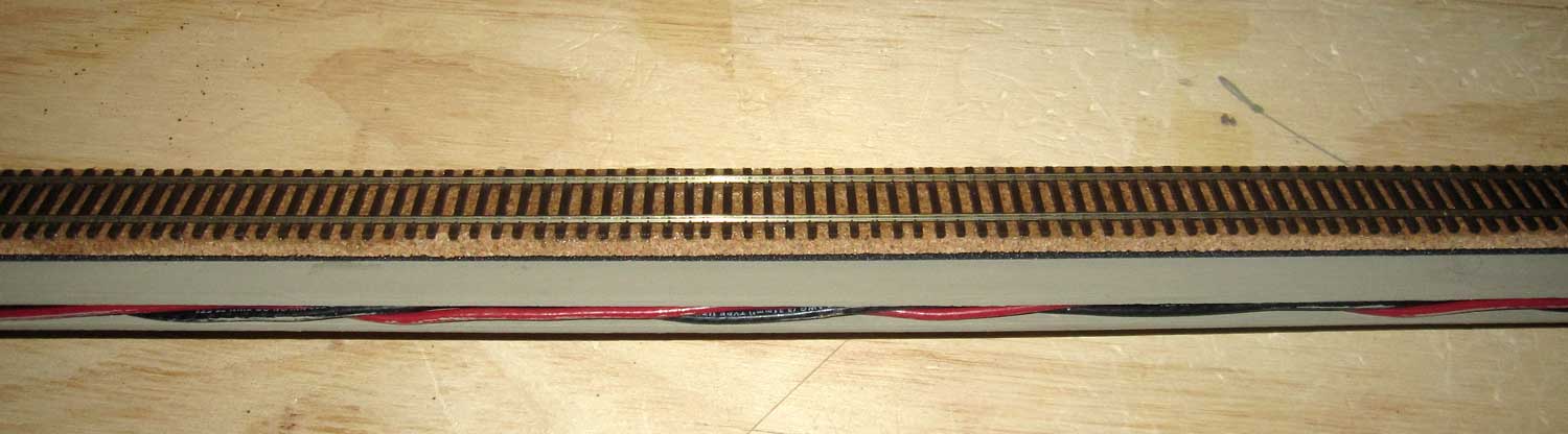
I used two sets of bus wires, a track bus for DCC track power, and an accessory bus for all other electronics and frogs. This arrangement retains control of switch points and frog polarity in the event of a short on the track bus. The track bus runs along the back edge of the benchwork, while the accessory bus runs along the front edge of the bench. The separation ranges from 8 to 14 inches, depending upon the width of the bench. Bus wires are red and black insulated 12 AWG stranded copper. The bus wires were twisted at a nominal three turns per foot, then threaded through holes in the benchwork and connected to terminal blocks at both ends. Spade lugs are used for all wire connections to terminal blocks, and they are crimped rather than soldered. ScotchLok #902 or #567 insulation displacement connectors are used to connect short lengths of insulated 16 AWG stranded copper wire runners to the bus wires. ScotchLok #905 insulation displacement connectors are used to connect the insulated 22 AWG solid copper rail feeder wires to the runners. Feeder wire is red and black for tracks and green for frogs. Switch motor wires are insulated 18 AWG stranded copper with black (-) and white (+) insulation. The Switch8 and Button Board data wires are yellow insulated 18 AWG copper. Wires are bunched at the holes in the benchwork and/or secured with cable clamps. Where I had to choose between neat wire bundles and shorter wire length, I generally choose shorter wire length.
With the bus wires in place, the first step in preparing the layout for wiring is to install the feeders and switch motors as described last month. Next, the component boards are screwed to the underside of the bench with care to orient the terminal blocks for the shortest wire runs to the track bus and accessory bus. The bus wires are connected to the boards, followed by the track feeders, and finally the switch motors, making sure that the white motor wire runs through the resistor board.
The Switch8s and SwitchIts must be programmed for accessory command control until the control panels are built and wired. I numbered the turnouts consecutively, and used those numbers for accessory commands. Next, verify that the normal and reverse positions of the points match the accessory positions. If not, they are reversed using CV settings on the DCC system. For operation, I wrote the switch number on the roadbed beside the throw bar, but by the time I’m ready to put down ballast and ground cover, I will have built and installed the control panels, so the accessory commands won’t be required.
The following series of photographs show the boards after they have been installed under the layout.
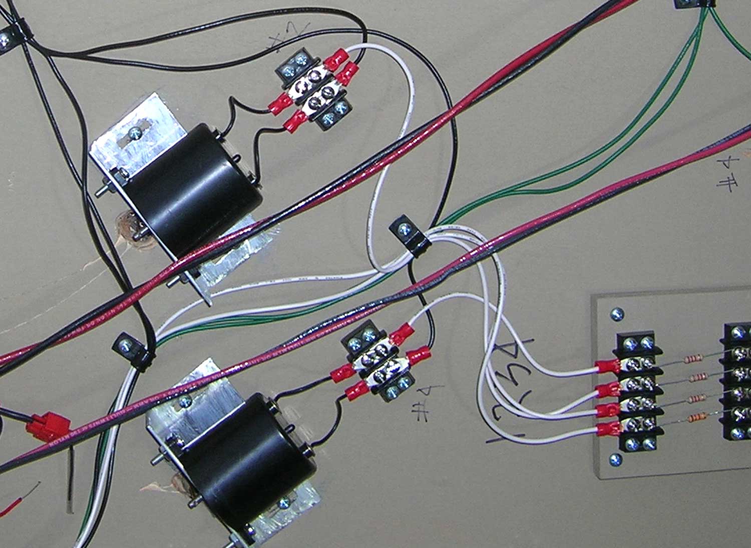

SwitchIt, Dual Relay, and resistor boards wired to bus and switch motor
I have not designed the control panels at this point. The goal is to cascade the switch motors for Chicago and Denver to provide route selection to make it easy for operators to move trains in and out of staging. Switch motors at Burlington, Winfield, and Washington will be controlled by toggles or push-buttons mounted on local control panels. The remaining switch motors will be controlled by fascia mounted toggle switches.
I will update the wiring and control information as it develops. The next post will address layout lighting.
Thank you, Nelson, for your latest update. Here are links to Nelson’s previous layout posts.
We will feature more progress in upcoming blog posts.
Questions and comments can be posted below. Please follow the instructions so your comment can be posted. All comments are reviewed and approved before they appear. To subscribe to this blog, enter your info for a comment and check the last box to notify of new posts by email. Share the blog link with other model railroaders.
Actually Jared, the wiring is quite simple, since it’s just an extension of the terminals of the NCE boards. Trouble shooting only involves determining which board or motor needs replacing.
One correction has come to my attention, the boosters are 5 Amp, not 5 Watt. I missed that correction during proofreading.
Dear Mr Moyer,
Your workmanship is outstanding!
Thanks for taking the time to document your railroad model in detail.
I have used suitcase connections on some very complex layouts. I strongly suggest east real wire go to either a screw terminal strip or a wire nut before going to the bus via the suitcase connector. Otherwise if you have a short you cannot disconnect each piece of track separately. This will be a major pain for trouble shooting if you cannot easily disconnect each track piece- not just each block
John Rogers. Butte Montana
I’ll second what John said, I learned the hard way that having connections that are easily separated and joined quickly are essential in being able to maintain a layout.
I solder track joints within each block. The track plan is simple, and the blocks are fairly short , e.g. a yard track, passing track, spur, etc. Since I can’t isolate each piece of flextrack easily, there is no advantage to additional complications like wire nuts or more terminal blocks. I do see the advantage on a large layout like a club layout where several members of various skill levels lay and wire track. I use construction adhesive to lay track, so no spikes are used, thus eleminating a prime source of mysterious shorts.
Very neat and well documented which will be a great aid in the future when needed.
Carrumba! There’s a jungle of wires underneath that layout. You’d have to be an electrical engineer to install and maintain that. It is certainly above my pay grade. There’s a reason I model a branchline with 22 handthrown turnouts.