The Helix – Around and Around and It Comes Out Here
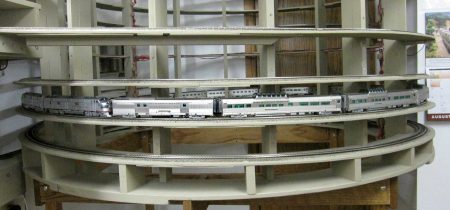
Nelson Moyer has been busy building his CB&Q layout. His latest adventure has been building a helix. Here’s Nelson with his tips and techniques. Click on any image here to review a larger size.
Multi-level layouts are becoming more popular as they permit longer runs with more towns, sidings, industries, and thus more switching opportunities in a given footprint. The Burlington-Washington Subdivision of the Chicago, Burlington, and Quincy Railroad ran 53 miles Northwest from Burlington to Washington, IA, with trackage rights on the Chicago, Rock Island, & Pacific from Burlington to Mediapolis, IA, and on the former Burlington and Northwestern tracks from Mediapolis to Washington. The branchline passed through seven towns more or less equally spaced along the route. My goal was to model as many of those towns as I could accommodate in a 13 x 16 foot room.
The evolution of the track plan is described in Part 1 of this series . Briefly, trains left Burlington and worked Roscoe, Yarmouth, Mt. Union, Winfield, Wyman, Crawfordsville, and Washington. Havre, just Southeast of Washington, was a passenger flag stop. By placing towns along two walls of the branchline room and on both sides of a central peninsula, I could accommodate four towns on each level. However, Washington is the terminus of the branchline, and it had a wye for turning motive power, a requirement in the days of steam. Washington was also the most interesting town in terms of size and switching potential.
In order to do justice in modeling Washington and include the wye, I would need to use the entire level 2 peninsular surface. At first blush, this didn’t appear to be a problem, as there were only seven towns. However, two of the most interesting scenic objects on the branchline are located just northwest of Winfield, IA. A 105-foot pin-connected Parker through truss bridge with a five span pile trestle on the Southeast end was built in 1879 to cross Crooked Creek. Just one mile further up the track was a 158-foot, fourteen span pile trestle with a deck girder bridge over County Road 105 and it crossed Lemon Creek. That meant I had to choose between modeling Wyman or the bridge and trestle. I chose the latter.
What has all this got to do with the helix, you ask? A lot. The track plan provides for an eight track staging yard under levels 1 of the branchline. The helix was designed to connect Burlington to points west on the CB&Q mainline (Denver on lower level staging with a reverse loop), points North (RI tracks to Minneapolis-St. Paul) and South (the K Line to St. Louis). This enabled operating trains from Chicago through Burlington to Denver (both are staging yards), and from St. Louis to Minneapolis-St. Paul (a hidden run through track connecting the North and South ends of Burlington with a passing track and reverse loop), as well as traffic on the Burlington-Washington Subdivision (branchline levels 1 and 2). This meant the helix would drop down three turns to service Denver, and rise up four turns to go between levels 1 and 2 of the branchline.
Additionally, the K Line is at the same elevation as Burlington, and the K Line and the reverse loop are between the helix turns that go either up or down. The bridge and the trestle on level 2 of the branchline must be at a higher elevation than would otherwise be required because it was not feasible to use a drop down type installation for the creeks and trestle bents. This would have encroached on level 1 scenery to an unacceptable degree, as deck separation is only about 12-inches. This meant that the level 2 helix exit must be one turn higher in order to raise the right of way enough to accommodate the trestle bents. Modeling Wyman would have been much easier, but also much less interesting.
The only location for the helix was in the alcove in front of the bathroom door. The space measured 61-inches wide. I wanted to maintain a 30-inch minimum radius on the main line, but this space limitation forced some creative engineering. I plan to run full length passenger cars through Burlington, so those trains have to negotiate the helix. I measured the overhang to determine that the maximum radius providing clearance on three sides of the helix to be 29-inches. That didn’t allow for outside supports on the helix loops. I designed a system for cantilevering the helix turns using inside supports. Because I wanted to keep the grade at or below 2%, I had to keep the thickness of the turns at an absolute minimum, while providing structural support and maintaining vertical clearance for rolling stock.
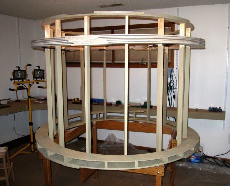
The helix rests on a framework of oak. The 1 x 2 vertical support members rest on a ring cut from ¾-inch plywood placed on top of the oak framework. Another ring cut from ¾-inch plywood stabilizes the top of the vertical support members. This construction provides a ridged frame upon which to suspend the turns of the helix.
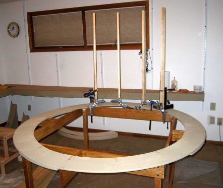
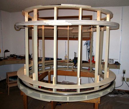
Here’s a beginning look at the work. The base is built using oak lumber. The support ring was cut from ¾-inch plywood in quadrants and glued together with ¾-inch splice plates. The vertical supports are 1 x 2 pine. The first set of turn quadrants appears in the background.
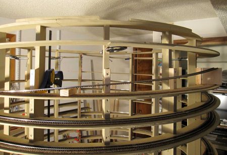
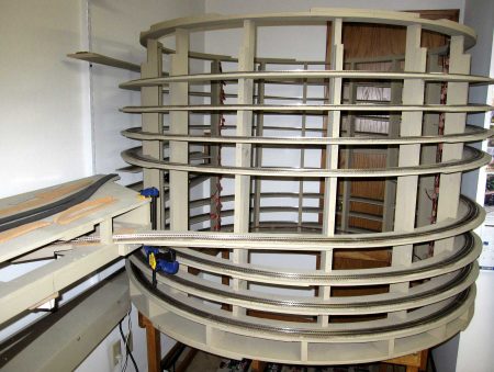
The support frame was constructed first. Experimentation indicated that fifteen vertical supports spaced equally around the ring provided sufficient structural integrity to eliminate sag between supports. The helix turns were cut in segments from ¼-inch Baltic birch plywood. Splice plates for connecting quadrants of each turn were cut from 1/8-inch Baltic birch plywood. A piece of 1 x 6 pine was ripped to produce spacers to fit between turns. The turns were built in place on the base ring and around the cylindrical framework, one at a time, until all eight turns (including the reverse loop) were complete. After all turns were finished, they were raised to the top of the cylinder and clamped out of the way until needed.
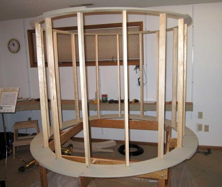
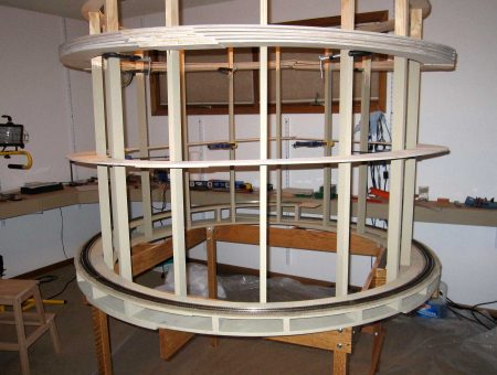
Here’s the finished support cylinder with fifteen vertical supports. The stabilizing ring at the top was cut from ¾-inch plywood in quadrants that were spliced together.
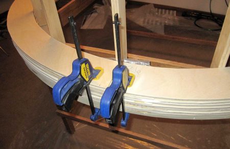
The roadbed turns were cut in quadrants from ¼-inch Baltic birch, and they were assembled on the base ring around the support cylinder by gluing the quadrants together using a splice plate cut from 1/8-inch Baltic birch plywood. Wax paper was placed under the splice plates to prevent glue from sticking to the turns below. All eight turns were built sequentially in this manner.
The finished turns were elevated to the top of the support cylinder and clamped out of the way of subsequent construction steps. The first turn was blocked up to a 1.8% grade. The plywood and risers were painted before proceeding to lay roadbed and track.
The next step involved establishing the grade for the first turn. Calculations in 3rdPlanIt determined that the grade should be 1.8%, so spacers were cut in various lengths to block up the first turn. A digital level was used to establish the desired grade, then the elevation was measured at the fifteen vertical supports, and permanent spacers were cut and glued in place. After the first turn was installed, the plywood was painted, cork roadbed was glued in place, and the track was laid using construction adhesive.
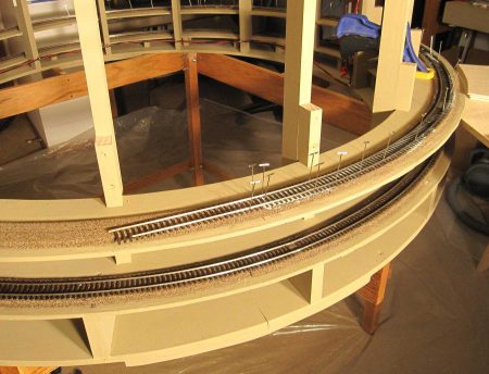
Commercial cork roadbed was used for ease of installation. Both roadbed and track were glued using construction adhesive. Feeder wires were installed before proceeding to the next turn (not shown in this photo).
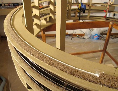
This close-up shows the adhesive for installing the roadbed and track. A 3-foot bead of adhesive was laid down on the sub-roadbed and spread with a 1-inch putty knife before applying the first half section of cork. The cork was held in place by the adhesive and T-pins until set. The same process was used to lay track. The adhesive is white initially, but dries clear.
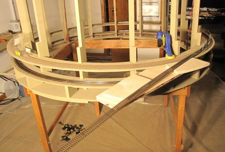
Because all track in the helix is curved, I developed a system for soldering the next section. I left a tangent on the end of each curved section, clamped a temporary support to the bottom of the turn, blocked up the track to sub-roadbed level, installed rail joiners, and soldered the new section to the tangent.
The track was then bent to a 29-inch radius (leaving a four inch tangent at the end for the next section), and then it was blocked up to permit application of adhesive to the cork roadbed with a putty knife.
The track was lowered onto the adhesive and held in place with T-pins until the adhesive set. The rails were cut to equal lengths, and the next section of track was soldered using the method shown two images previously.
At this point, the next turn was lowered into place, and glued to the first turn with a splice plate between them. All spacers from this point were of uniform length to maintain the grade established with the first turn. The second turn was painted, and the process was repeated for each of the first three turns.
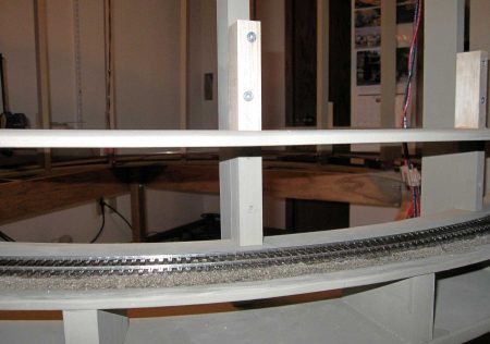
The first turn was blocked up using measure, cut, and fit. All other riser blocks were the same size to maintain turn clearance at the established grade of 1.8%. The top and bottom of the risers was angled by the number of degrees equivalent to that grade. The risers were glued and screwed to the turn below and to the vertical supports.
This close-up shows how the risers support the cantilevered turns of the helix.
The reverse loop was installed at a constant elevation to match the level 1 base elevation of 49-inches. The four turns required to reach branchline level 2 were installed using the same techniques as the first three turns.
There are three entrances and exits on the helix. The Denver staging entrance is at 43-inches and the exit is at 32-inches. The K Line entrance and exit are both at an elevation of 46-inches. The branchline entrance is at 49-inches and the exit is at 67-inches though the level 2 benchwork is at 63-inches. The four inch difference is to accommodate the bridge and trestle, and the elevation drops to 63-inches at Crawfordsville and remains at that elevation to Washington.
The bus wires were installed at the bottom of the vertical supports and split into a T, with the two legs running up vertical risers on either side of the cylinder. The feeder wires had been installed when each turn was installed, so that they could be easily connected to the bus wires using insulation displacement connectors (suitcase connectors). The helix bus wires were connected to the booster through a circuit breaker.
Designing and building the helix was definitely an adventure in creative engineering.
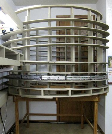
The completed helix is shown here, including the reverse loop for the K Line. The other entries and exits had not been connected when this picture was taken. The bus wires and feeder connections are shown on either side of the helix.
Here’s an overall view of the completed helix as an eleven car 1952 California Zephyr climbs out of Denver staging Eastward with two E-7s on the point.
Next installment I’ll talk about the duckunders and liftouts. That was originally planned before the helix adventure, but unforeseen circumstances pushed it back a month.
Thank you, Nelson, for sharing your helix construction details. Here are links to his previous layout posts.
Layout Design with Nelson Moyer – Part 1
Overcoming Adversity – Part 2
Roadbed and Track – Part 3
Layout Wiring – Part 4
Layout Lighting – Part 5
We will feature more of Nelson’s progress in upcoming blog posts.
Questions and comments can be posted below. Please follow the instructions so your comment can be posted. All comments are reviewed and approved before they appear. To subscribe to this blog, enter your info for a comment and check the last box to notify of new posts by email. Share the blog link with other model railroaders.
So are the verticals about 13″ apart?
The verticals are spaced at 9.5 in. (range 9.25 to 9.75 in.) measured along the inside of the support ring. Most are spaced exactly 9.5 in., but 9.5 isn’t an exact multiple of the inside circumference, so there’s some variation.
Dude that helix is YUGE! 😀 Well done.
Back when I was having John Armstrong design my Alma branch layout I wanted a plan that would incorporate a helix so I could build a 2 level layout. John strongly discouraged it and I ended up building the one level 22 1/2’x30′ that he finally designed for me. In retrospect I am glad I did not build the double-deck layout I envisioned. John was able to get in the seven stations and all the trackage I wanted. It’s a good layout. A double-deck layout with a helix would have been a booger to build and, as it turned out I didn’t need a second level.
Branch line track plans are usually simple, towns have a passing track and a couple of spurs, so if you use the track charts for your railroad, why did you need John Armstrong to fit seven small towns into 675 sq. ft. of basement? My branch room is 208 sq. ft. less 44 sq. ft. for the closet where my workbench resides (19 sq. ft.) and the space taken up by the helix (25 sq. ft.), leaving only 164 sq. ft. for my towns and aisles. That’s 24% of your space, so I think you can see the advantage of a triple deck layout with staging on the bottom and two levels for my six towns. As for designing and building a double deck layout with a helix, it depends upon your skill set or how deep your pockets are. My track plan follows the CB&Q track charts exactly, albeit with severely truncated lengths. I used Tony Koester’s layout design element concept for each town module, and simply strung them together between Roscoe and Washington, omitting Wyman so I could I could model the Parker pin-connected through truss bridge over Crooked creek and the long trestle with a deck girder bridge over Lemon Creek and CR 105. I would have liked more space, but I took what I had and made lemonade.
Amazing work…I admire Neson for his talent and ability in doing his railroad work.
Excellent.