Eric Hansmann picked up a Resin Car Works HO scale UTLX tank car kit at RPM Chicagoland and built it to kick off a new year. Here are his notes.
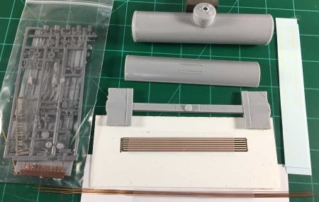
I decided to push my kit building skills forward by building my first resin tank car kit. After building several box cars, gondolas, and flat cars, I thought a tank car should be added to my 1926 fleet. The image above illustrates the main kit components, including the decals along the right side of the photo.
Resin Car Works provides extra files on their website to assist in building their kits. The details for these UTLX Class X-3 tank cars were most helpful.
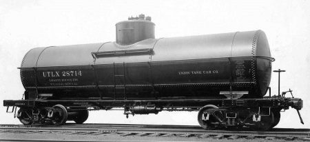
The Union Tank Line introduced the X-3 tank car design in 1917. This Resin Car Works kit most reflects a series of 10K gallon capacity UTLX X-3 tank cars built in 1923. The prototype cars were numbered as follows:
⦁ 27825 – 29324 1500 cars built by American Car and Foundry
⦁ 29325 – 29999 675 cars built by Standard Steel Car Company
⦁ 36500 – 36999 500 cars built by Cambria Steel
I started by opening the box, reviewing the parts, and reading through the instructions. Castings were cleaned of minimal flash. Holes were drilled and tapped for the trucks, and Accurail Proto:HO couplers were installed. Running boards, saddles, supports, and the main KC brake component were installed quickly.
The main KC brake casting is a Tichy Train Group part that requires attention to clean part lines and level the mounting pad areas for a secure fit. The rod connecting the cylinder to the clevis also needs to be shortened. Al Westerfield noted years ago that this part is cast with the piston extended in a full brake application. It is easy to slice the rod at the cylinder, drill a #75 hole into the end of the cylinder, then reinsert the rod and glue it into place with the clevis closer to the cylinder. This has become my standard procedure for all the K brake system installations using the Tichy components.
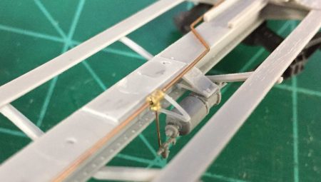
My 1926 focus means there are a few assembly steps for this kit that differ from building for a later era, such as installing a K brake system. Several prototype images were reviewed to determine the placement of the train line at each end of the car. The train line seems to go over the bolster before going under the end platform to connect with the air hoses. This varies from the instructions.
The train line wire was bent and installed with the union to attach the brake system feed. The feed to the brake system is a first for me. The wire for the connection should be heavier but it’s more difficult to attach to the Tichy part at the right place. The wire is installed on the back side of the part near the bottom. Yup, it’s a cheat.
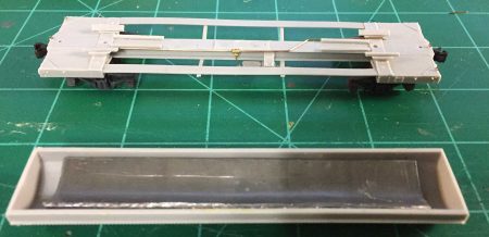
Sheet lead weight was added to the bottom of the tank casting, as seen in the foreground of the above image. Barge contact cement was used to attach the lead in place. Two layers of the lead sheet were installed and the plenty of time was allowed for the contact cement to gas out before gluing the tank shell together. The completed model weighs three ounces. This is a half an ounce less than the NMRA Recommended Practice but I prefer slightly lighter models.
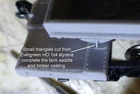
Before continuing further, there are a few small details that are easy to install at this point. These were missed in the instructions. Small triangular gussets should be installed beside the tank saddles. Steve Hile sent the above image that illustrates the location. One small triangle per gusset will reflect the prototype.
While the contact cement was setting up, I needed to create a part for the KC brake system. the main cylinder is bolted to the same hanger used for the AB brake cylinder but the air tank end needed a bracket. I used a thin strip of Mylar to create the angled bracket, as seen in the above image just behind the air line union. The image also illustrates the feed line placement from the air line to the air brake components.
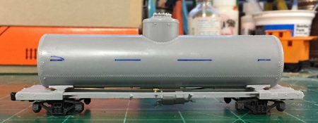
Progress cruised right along the following day as the main tank components were glued together, followed by the dome hatch and safety valves. Holes were drilled on the tank and frame for grab irons. The blue lines on the tank are marked for the upcoming handrail installation.
The tank was attached to the frame using Barge contact cement. Cyanoacrylate (CA) will be applied to a few spots after the Barge cement sets up. The tank bands are next and I’m a bit anxious about installing those. It’s one of the more intricate parts of the build. At least, that is my perception.
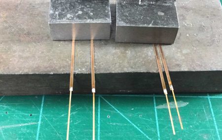
Part of the tank band installation involves soldering wire to the ends of etched metal straps. I had difficulty achieving a decent solder joint between these two components. I used flux each time but the metal parts must have been oxidized. In the end, both the metal band and the wire needed to be cleaned to a shine to get a good solder joint. Cleaning them to a shine was the key to making progress. Once the solder joints cooled, the flux was cleaned off with a cotton swab soaked in 91% Isopropyl alcohol.
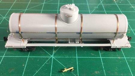
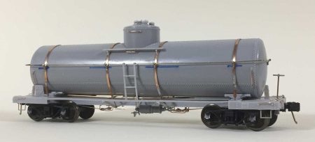
Installing the tank bands on the model went smoothly. The above image shows the wire from the two center bands twisted together to tighten the strap onto the model. CA was carefully applied beside the bands on the tank and capillary action pulled the liquid under the band. The extra wire will be snipped after the glue sets overnight.
The above image also illustrates a part that was not in the directions. There are two straps on the prototype that span the width of the car and attach to each running board at the same point as the crossbearers. These straps go over the top of the center sill and should be installed about the same time as the crossbearers. While not impossible, it is a challenge to install these after the tank has been glued onto the frame. The same etched metal material for the straps was used for these other straps on the underframe.
Handrail installation is next. I used pieces of clear tape to cover the strap area where the holes need to be drilled. An awl was used to create a starting point for the drill bit. Take your time drilling the holes through the straps. They need to be centered on the strap and the bit can easily wander off the metal to the resin tank.
At the foreground is a small sprue with an extra Precision Scale brass stanchion. The most tedious part of this step is carefully filing the mounting post on these to fit the #76 hole in the tank straps. You can’t enlarge the hole or you might break the strap. Additionally, it is very easy to mount the stanchions upside down! Consult the prototype UTLX images before installing the first stanchion.
BTW, the Precision Scale brass stanchion part is #32110. I need to get more of these to upgrade a few Proto2000 tank cars. The plastic handrails on those models need to be replaced.
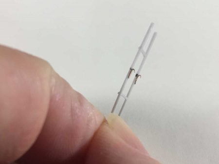
The dome step and ladder are next. As I model 1926, these details differ slightly from the kit instructions. A main visual difference is the ladder. It ends at the handrail and is attached to it. Small hooks were made from extra tank band material and mounted on the back of the ladder stiles to loop over the handrail. The etched metal was cut in half length ways with small scissors. One end is bent around the same diameter wire as the handrail and then trimmed. The image above shows the part before the upper portion of the ladder was trimmed just above the hooks.
As the ladder does not reach the dome step, a grab was installed under the step.
The brake roads and levers were installed next. Inspired by Bill “Xxtreme Modeler” Welch, I used the turnbuckle castings included in the kit to use as clevis’ for the brake rod connections. Only after installing these did I realize I did not thin the castings as Bill had instructed. I consoled myself with a cold beer.
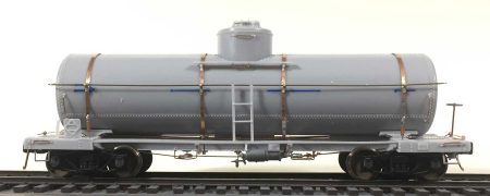
After installing the placards and uncoupling levers, my first resin tank car kit build was done! It will soon head to the paint shop but will see some action on the Wheeling Freight Terminal before paint is applied. A pair of Tahoe Model Works Andrews trucks are on order and will be installed after the model is painted. It looks great on the rails.
Other modelers have built, painted, and decaled their Resin Car Works UTLX tank cars. Lester Breuer finished a couple of these tank car models. Here are Lester’s notes on finishing his models.
The models were washed with water and Dawn liquid soap. After drying, they were attached it to a painting stand I built following an article in RMC several years ago. Polly Scale Engine Black # F414290 was sprayed over each of the models and time was allowed for the paint to dry. They were then sprayed with Model Master 4638 Gloss Clear Acryl as a decal prep surface. After the decals were applied and dry, I spray Model Master 4636 Flat Clear Acryl. Trucks were brush painted with PollyScale Tarnished Black # F414140.
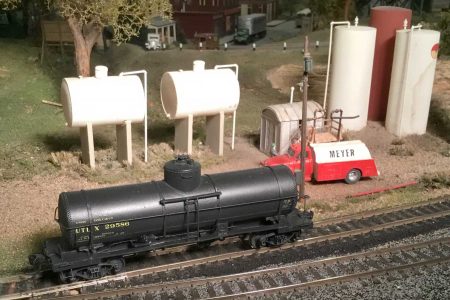
The in service photo is taken at Meyer Oil on my Minneapolis & Northland Railroad Company.
Thanks to Eric for assembling this Resin Car Works UTLX Class X-3 tank car build summary. Thanks also to Steve Hile and Lester Breuer for additional photos and notes.
Questions and comments can be posted below. Please follow the instructions so your comment can be posted. All comments are reviewed and approved before they appear. To subscribe to this blog, enter your info for a comment and check the last box to notify of new posts by email. Feel free to share the blog link with other model railroaders.





I do hope you’ll bring the finished model to Greensburg in March.
Eric,
Congratulations on a great job in your new adventure. I hope this inspires other resineers to elevate their skill level, too.
Hoping to see more tank cars on this list.
Wonderful job, Eric! An inspiration for those of us with parts still in the box.
A question for Eric or Lester – what thinner do you use with your Model Master Clear Gloss and Clear Flat?
Thanks
Pete
Pete for some time I used distilled water only; however, at times I lost the character of the paint ( it became too thin ). I now use a custom mixed thinner I mix using a formula provided by Joe Fugate, Model Railroad Hobbyist. It is a mix of distilled water, airbrush thinner and acrylic flow enhancer. You can find the formula in the Guide To Acrylic Painting by Joe Fugate on the Model Railroad Hobbyist magazine website after becoming a member which is free. Pete I can not provide formula percentages here as that would violate copyright rights.
Lester Breuer
Hi Eric,
Beautifully done – pictures of assembled car could be confused with an O scale model!
Rick
Eric, you did a great job on this tank. Your well documented instructions and tips will help myself and I am sure others in getting their tank cars built. Your assembly of this model was top notch, looking forward to see it painted and weathered.
Thanks for sharing
George Toman