Jerry Hamsmith brings us another installment on building the Resin Car Works New York Central gondola kit.
With the underframe details complete, it’s time to add detail to the car body.
Installing grab irons
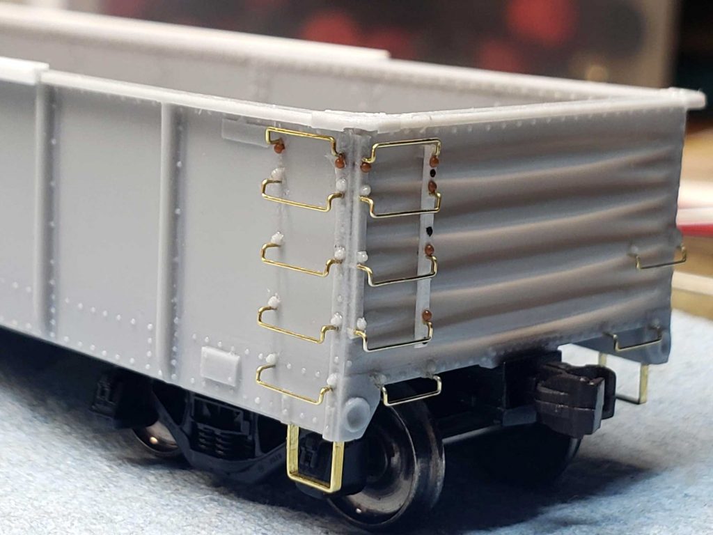
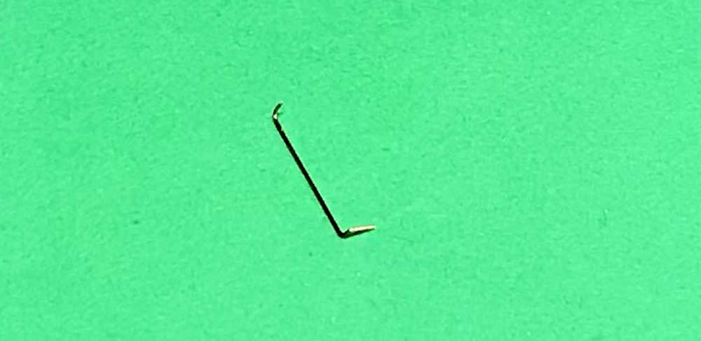
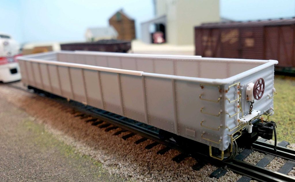
Remember the comments made about the hand hold fittings (from part one of this build) ? Holes were drilled slightly to the inside of center below the rivet detail cast onto the car body. Being aware that the extra length of any grab iron would protrude into the inside of the gon body, the grab legs were trimmed to approximately 3/64-inches before installing to alleviate that problem. Three members of the group used the kit supplied formed drop grab irons. One member decided to create his own from 0.010-inch diameter brass wire. Some members of the group also used a 0.030-inch spacer when inserting the grabs to assure equal space from the car body.
There are two drop bottom grab irons on the left end of the car side, five along the right (ladder) edge, four comprising the ladders on the left corner on each end, one on the right side of each end, and two at the bottom sill line on each end. That is a total of 28 drop grab irons, or 56 holes to be drilled. As mentioned in the first part of this build, I drilled some of these holes before starting the brake system work. The remainder were drilled as the body work was begun.
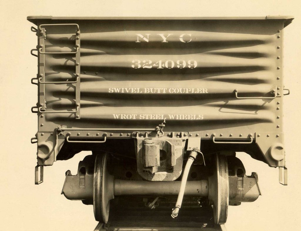
The top ladder grab on the sides and ends of the car are inverted. The placement of these grabs is unique, as the prototype photos show them being attached above, not below, the rivets. Additionally, the grabs do not extend above the top chord of the car. Various options were considered by the group for these details. We could ignore the rivet error and drill below as for the other grabs. Or we could shave off the misplaced rivet, drill the hole and either leave the rivet off or glue it back in the correct spot. Another option was similar but to drill the hole for a replacement Tichy 0.020-inch rivet.
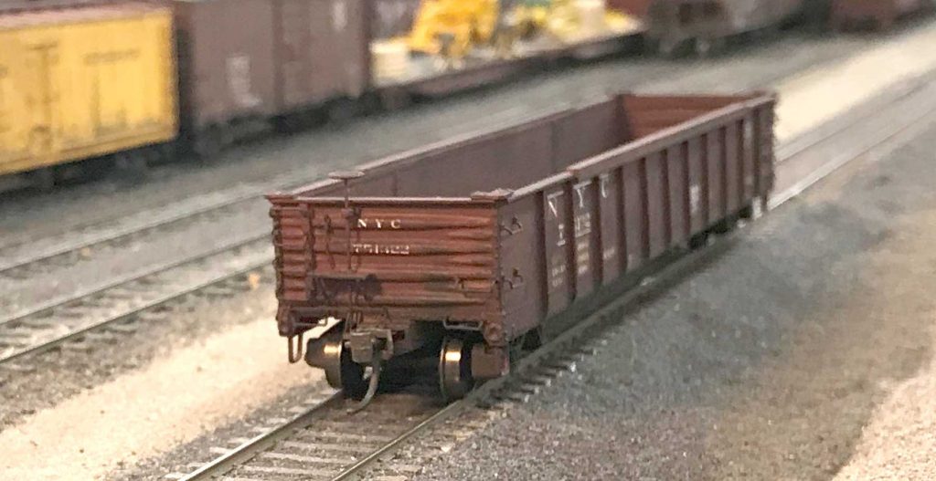
After installing the grab irons, a stiffener was added to the top side chords as in the prototype photo of 751478. Everyone in the group models 1948 or later, so this feature was considered an appropriate addition. Evergreen 0.080-inch angle was used and cut to fit between the eight middle panels of the side.
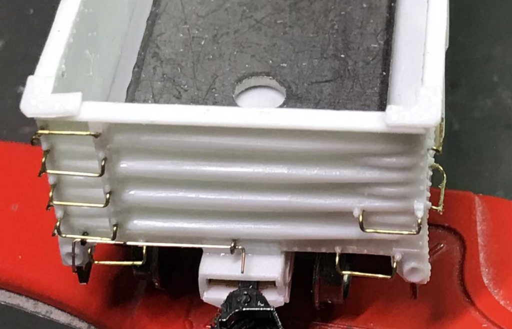
The A end of the car was finished next, requiring the addition of the top mount cut lever. Holes were drilled for the two eye bolt attachment brackets. These were about 4.25 scale feet apart. Per the prototype, the outer bracket is slightly outside of the end grab iron and at the top level of the rivet strip. The inner bracket is centered over the coupler box. An eye bolt was glued into the outer hole – an eye bolt was not glued into the inner hole at this time.
The pin lifter was formed from 0.010-inch diameter brass wire (0.012-inch could also be used). The handle was first shaped, then 4.25 scale feet measured and a bend was made toward the coupler. This was inserted through the outer eye bolt. A second eye bolt was added over the end of the pin lifter. The eye bolt was inserted into the pre-drilled hole above the coupler and glued in place. The lifter bar itself was also glued to the two eye bolts.
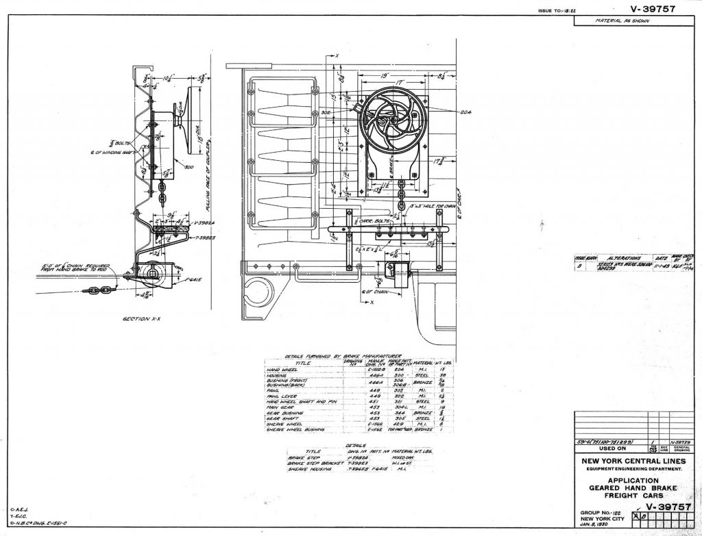
Details for the B end of the car were next. There were many options for the hand brake assembly as the NYC used five different installations on these cars. I created a chart that matched the type of brake and the rebuilt car numbers assigned. See the Kit Extras instruction files on the RCW website for files and prototype drawings.
B end brake hardware
Based on Official Railway Equipment Register data, we determined which cars remained in revenue service at our various modeling dates and the type of floor (wood or steel) used in those cars. Me and another group members chose a geared vertical staff handbrake. The other two Gondola Group members installed a geared power handbrake. Descriptions of each type follow.
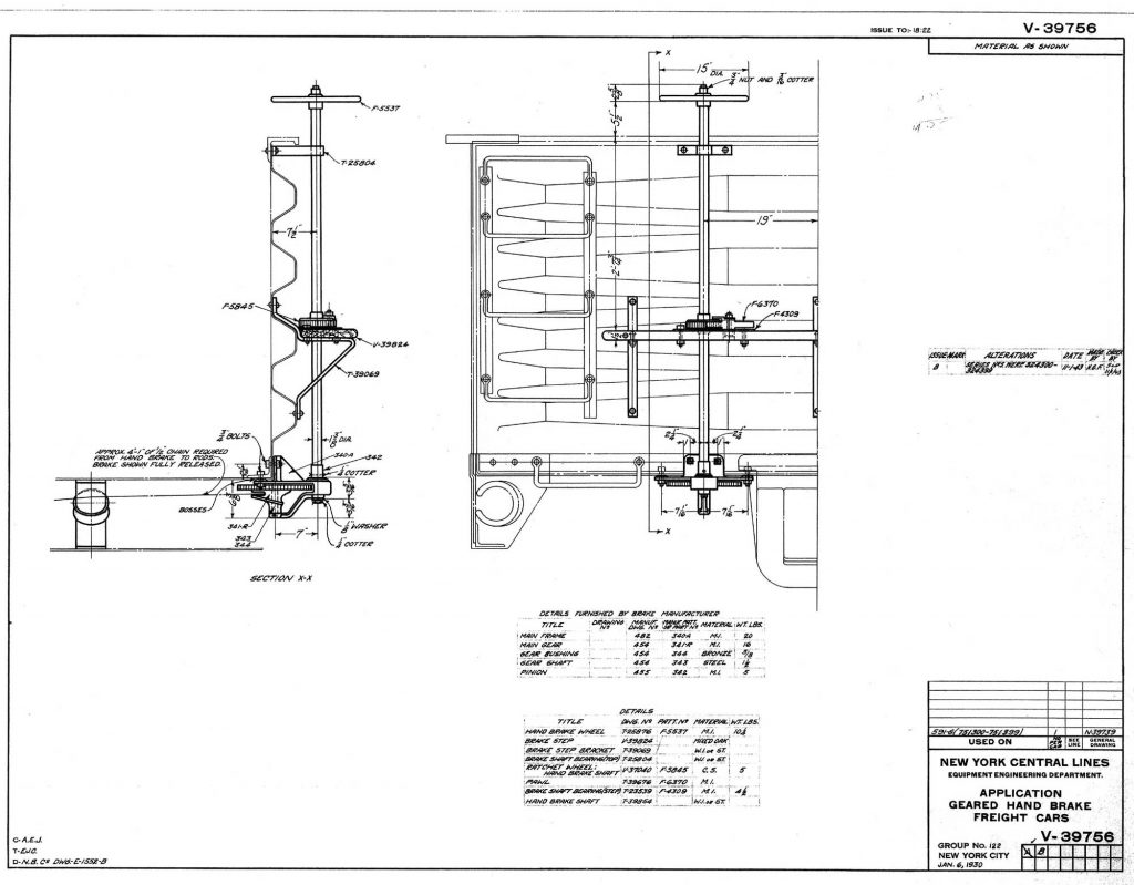
For the vertical hand brake assembly, the National Champion drawing was followed. The finished car would also need to be numbered between 751300 and 751399.
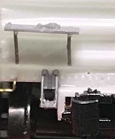
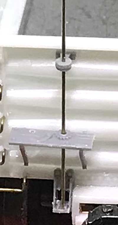
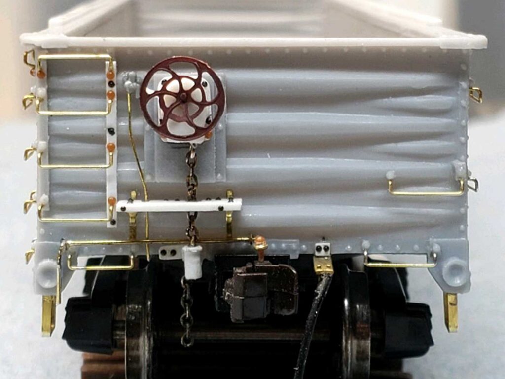
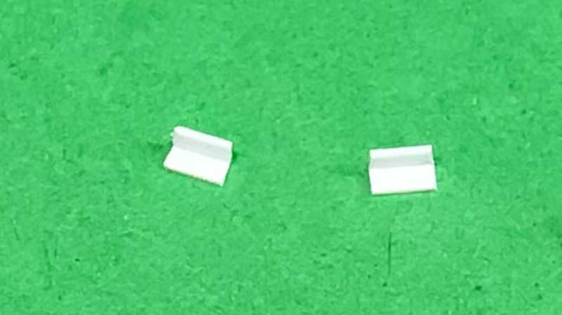
The components used were part of the Tichy brake hardware sprue included with the kit. The cradle, or boot, is part 24. The upper staff support is part 36. The brake step and step supports are also Tichy, as is the retainer valve. The photo above illustrates the parts, but the white retainer valve is an extra casting in the kit.
Following the drawing, the brake cradle was installed next to the coupler box on the bottom sill. The brake step came next with the staff hole oriented directly above the cradle. A hole was also drilled into the brake step for the retainer line of 0.008-inch diameter brass wire.
The prototype brackets extended from bottom rib to between the second and third ribs, with the brake step resting at the top of the second rib. The Tichy supports are not the same length so a compromise was made to provide the correct height for the brake step. Also, the brake step does not extend as far to the middle of the car as on the prototype, so the brackets were applied to fit the length of the model brake step.
To attach the top support, a piece of 0.012-inch diameter brass wire was inserted into the brake step and the cradle. The support bracket was placed over the wire and lowered into place, guaranteeing the vertical alignment of all three parts. The placement was marked, the wire removed, and the support was glued in place immediately below the top rivet line. The wire was reinserted before the glue set up to ensure alignment. The wire brake staff was removed to prevent damage as the rest of the build, painting, and decaling proceeded.
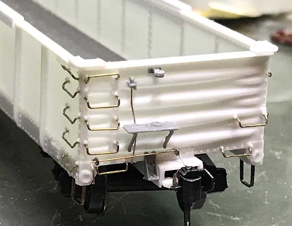
The Tichy retainer valve was installed next. Following the drawings, the prototype valve is just outside the outermost brake step support and the pipe comes from the bottom of the car, just inside the brake step support, through the brake step, and then veers slightly toward the outside of the car above the step connecting to the valve. The retainer pipe needs to be tight against the ribs and lower edge of the car. As such, it runs between the car and the brake step.
The uncoupling bar is added next, following the same steps as on the A end of the car. The uncoupling bar goes in front of the retainer pipe and behind the brake staff.
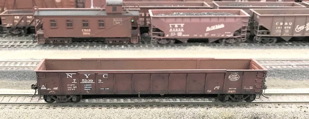
This photo of the completed B end shows all of the grab irons and brake gear applied to the car. The brake staff and wheel were added after the car was painted and decaled. Although compromises were made compared to the prototype, we felt the results were acceptable.
For the geared handbrake assembly, one member chose the Ajax geared hand brake and the other chose the Peacock hardware, which is described below. The finished car would also need to be numbered between 751100 and 751299.
Every effort was taken to follow the drawing. Very few of the kit parts were used. The brake step is 0.030-inch styrene supported by 0.010 x 0.030-inch flat brass strip brackets. The kit provided mounting panel was used but the supplied brake housing was modified to follow the Peacock design with a new handle added.
The bell crank is scratch built to mimic the builder’s photo. A brake wheel was found in a leftover parts box and slightly modified to resemble a Peacock wheel. Rivets and carriage bolts were added per the drawing. The Hi-Tech air hose is mounted on a Precision Scale bracket.
The retainer valve and pipe, and the top mounted cut lever were installed in the same fashion noted previously.
Tow loops
The tow brackets and loops were made from Evergreen 0.060-inch styrene angle and 0.010-inch diameter brass wire (0.012-inch could also be used). The angle is cut to about a one foot scale length – about three rivets on the car side. The prototype brackets were installed on the outside of the body, while the photos here show it attached to the inside. If attaching to the outside, new rivets will need to replace those that would be covered by the brackets.
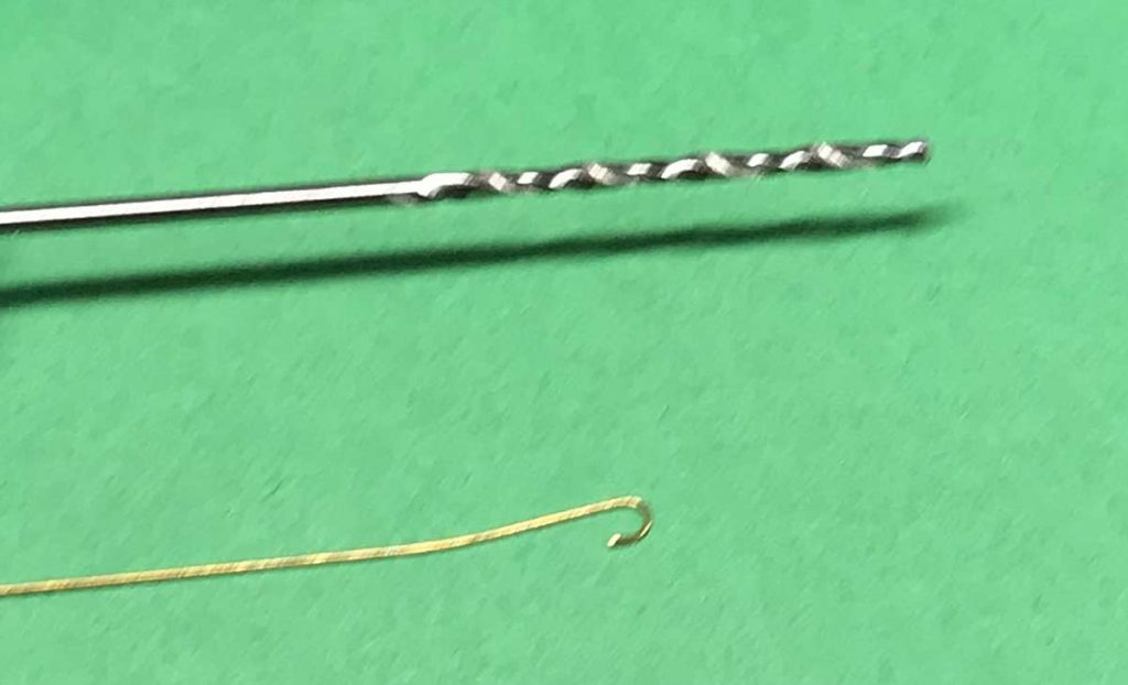
The loops are made by rolling the wire around a #56 drill bit. Each loop was cut to a 1/16-inch insertion length.
The loops were spotted on the car to determine the drill locations. After the brackets were glued into place, holes were drilled into the bottom of the bracket and the tow loops were attached.
The pressure release rod (bleed rod) shown in the photo was not added until the very end of the build.
After the body work was completed, everyone compared notes and we were ready to move onto the floor and the finishing touches.
Thanks to Jerry Hamsmith and his Gondola Group for these great detail installation tips and techniques. The adventure will continue soon as this NYC gondola kit build wraps up.
Questions and comments can be posted below. Please follow the instructions so your comment can be posted. All comments are reviewed and approved before they appear. To subscribe to this blog, add your email address to the function at the bottom of the right column on the main page. Share the blog link with other model railroaders.






Great job on all the versions built by the Gondola Group! Also great writeup on building the cars with attention to the small details.
Thanks for sharing
George Toman
Wow! This is absolutely great work. Sets the bar high for all us mere mortals.