Bill Welch has returned to wrap up his work on an MKT boxcar. Here’s the Xxtreme Modeler with an update.
I last reported on my MKT War Emergency model back in June 2018 and had to be reminded I needed to do an update. I’m sorry to leave people wondering what I did to finish its detailing and construction.
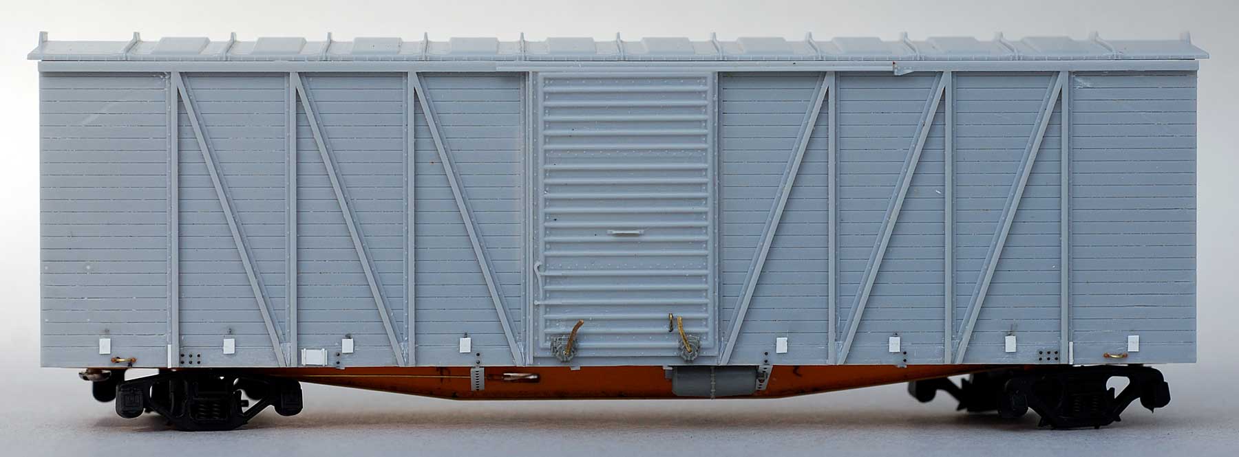
While obviously influenced by the War Emergency boxcar design there are some interesting detail differences I wanted to capture, beginning with the side grabs.

Photo courtesy of Gene Deimling.
Careful examination of prototype photos shows that these grabs are attached on one end to the steel ends and on the other end to the side sheathing. On the car body end the attachment bolt is over the grab while on the end attached to edge of the car end, the attachment bolt is in line with the grab.
On the left end of the side the attachment bolt for the upper grab is under the grab.
Note on the right end of the car where grabs form the ladder, the left end of the bottom grab is a drop grab.
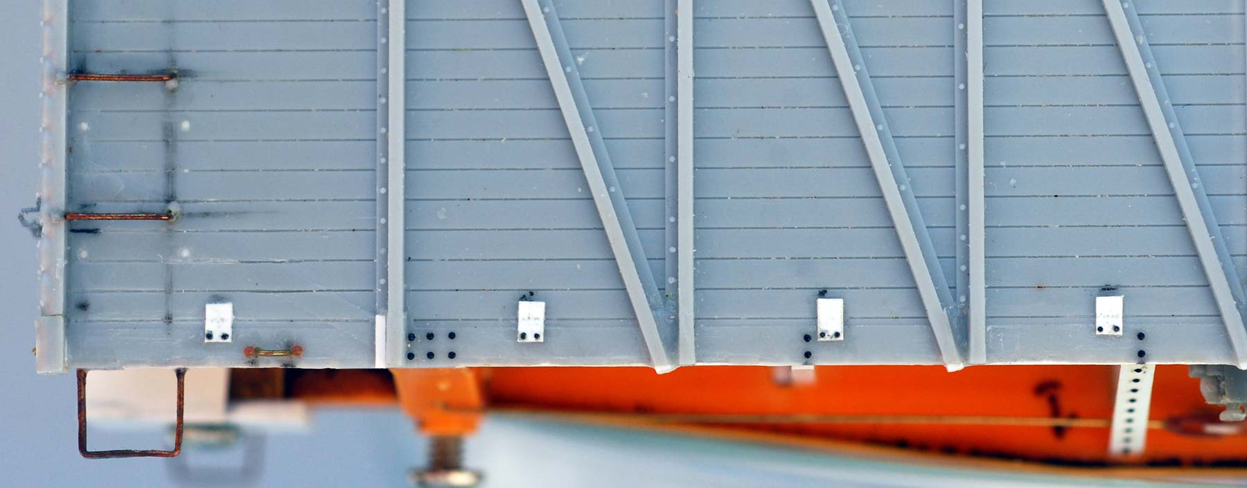
As you may know, by now I always want to try to create sill steps that are as close as possible to those on the prototype. A candle or lighter is used to anneal four A-Line steps and then manipulate/bend them to match what I see. Call me obsessive but as part of this manipulation I want square corners because the real thing has square bends. For this my favorite tool is the Xuron #575 Micro Forming pliers that has 90° jaws. The results can also be seen in these last two images.
This model is compromise since the body is about six-inches too short. This is because the new underframe must fit into the body deeper than the original. To make the end fit properly in relation to the rest of the structure I needed to shorten the end castings at the top and the bottom. While not perfect I think it looks natural. Before cutting along the bottom I drilled through the poling pockets and ran styrene rod in the holes to create gussets without any depressions because it seemed easier to do this before any cutting. I used an UMM razor blade saw to cut off the bottom just under the lowest rib or corrugation. The cutoff portion was set aside for the moment and another end was used to help mark each end about three inches below the top edge. Cuts were carefully made along the lines with the razor saw. I checked the fit up against the roof to make sure I would have a good joint for final assembly.
Now it was time to start adding things, beginning with plugging holes with styrene rod. I use a Precision Scale retainer valve for most of my models along the 0.010-inch diameter wire for its pipe. Although 0.008-inch would be more to scale, the 0.010-inch wire is easier for me to handle.
I flatten this wire size to make the pipe brackets. Typically, cars of this era with steel ends had wood linings. Bolts were used to secure these linings, so I have harvested more rivets to represent these bolt heads. The newly configured ends were about 0.005-inches short, so I used 0.005-inch thick styrene to shim the very bottom of the end and then attached to the salvaged gussets at the bottom of each corner. I also salvaged the grab iron attachment tabs from the part I cut off from the ends and spaced them along the bottom. When their joints were cured, the parts were drilled for the grab irons and harvested rivets were added for the attaching bolts.
Next, I made thin strips from 0.005-inch styrene and glued them along the face of the very bottom of the ends. These cars had a rather prominent buffer plate that was scratch built with styrene bits and larger rivets from an Athearn gondola. Once the buffer plate was glued in place, more rivets were harvested from an Athearn boxcar to detail the strip along the bottom. The Plano brake step is a Gypsum type with strips of 0.005-inch styrene used to form the braces with more harvested rivets. Lastly, sections of 0.005-inch styrene strips were placed to serve as mounting points for the end ladders.
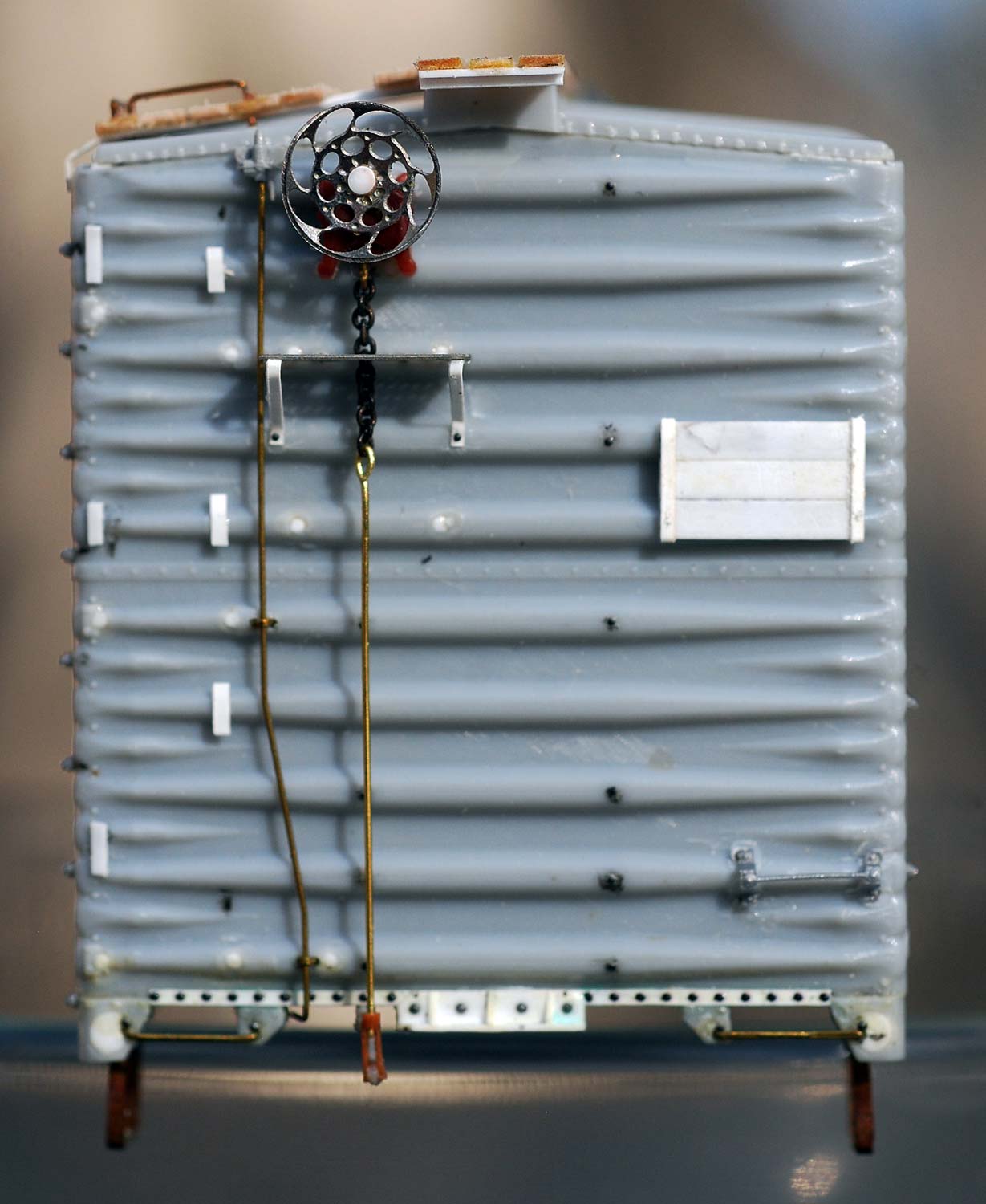
Here’s a look at the “B” end of the car with new details in place. Note the silver Kadee bracket grab iron on the right side of the end. This model will be painted Sloan Yellow, so I wanted to use a light color part in case the paint chips off. Kadee sells these but they are not cataloged. Contact Sam Clark directly to place and order. I know these are available in black, silver and two or three shades of green. There may be more colors, too. Ask Sam. (541.826.3883; mail@kadee.com)
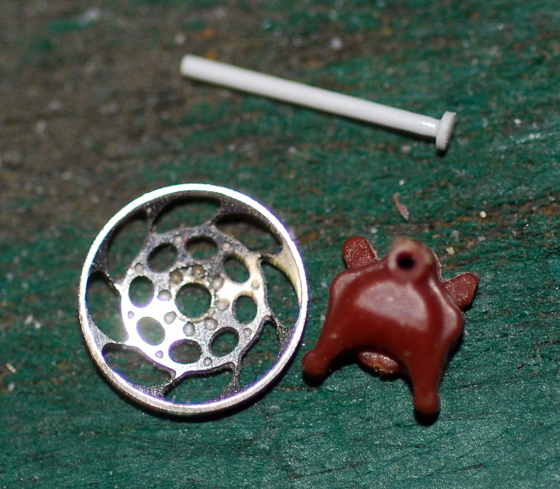
These cars used a Klasing handbrake and I have several originally available from True Line Trains with a Delrin brake gearbox with a gorgeous steel brake wheel. Delrin is difficult to glue but one of the assemblies presented an easy fix. The True Line wheel is assembled with a melted plastic rod. One of mine had come apart so I made a new version with styrene rod. The gearbox was drilled to accept this rod, and a similar hole was drilled into the “B” end to install the detail.
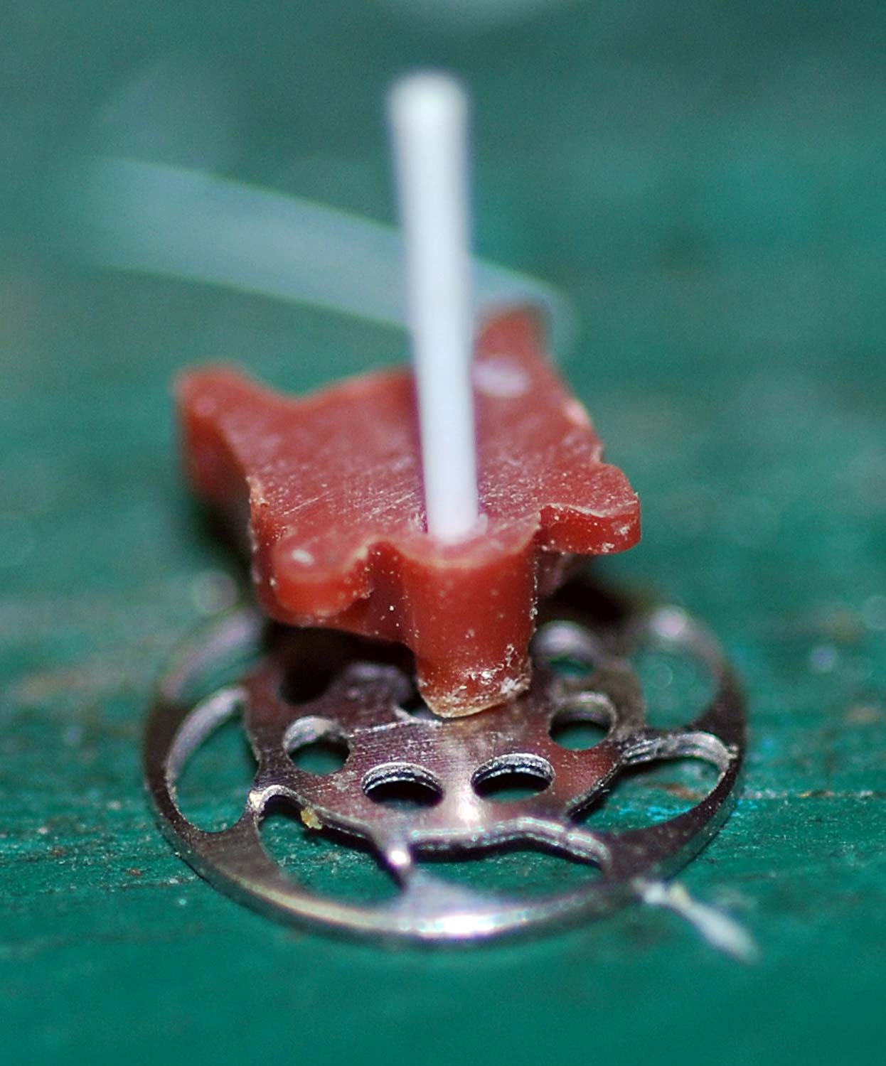
Here’s the assembled hand brake wheel and gearbox components. After checking the gearbox was square on the car end, Tester’s styrene cement was brushed onto the rod from inside the car body. More Tester’s was applied onto the styrene nob on the brake wheel to seal the deal. Unless the “B” end receives a very hard blow, the unglued gearbox is essentially locked in place. Given that this car will be painted in the familiar Sloan Yellow scheme, the fancy Klasing brake wheel will really show well.
These Klasing hand brake wheel parts are no longer available from True Line Trains. Resin Car Works offers 3D printed parts that can be used. Part DP 2.01, Klasing hand brake wheels and gearboxes, are listed on the RCW Parts and Decals webpage.
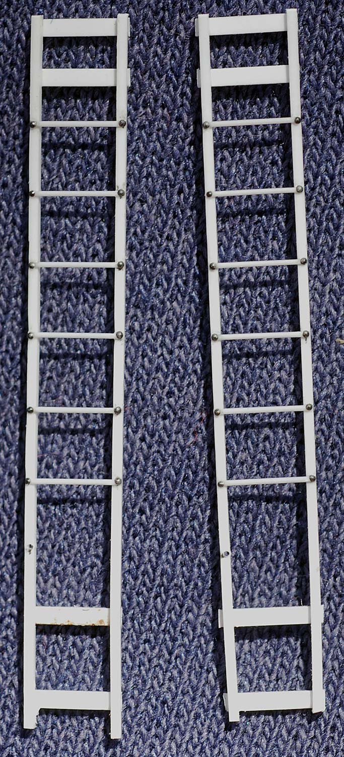
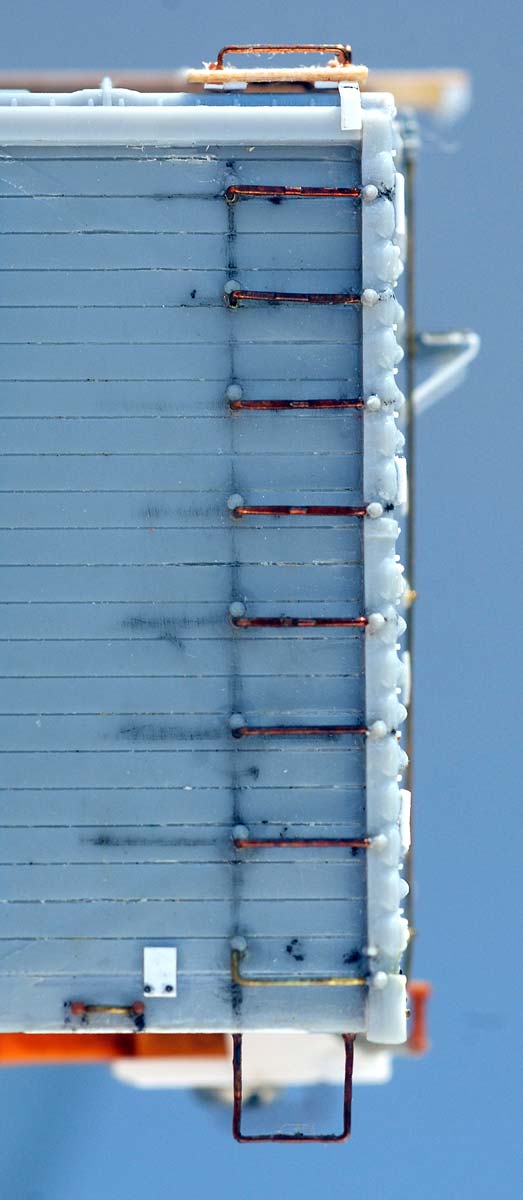
For a couple of years now I have been using Plastruct 0.010-inch styrene rod to replacing the rungs on styrene ladders. This model needed two end ladders to exactly match the grabs on car side corners. Harvested rivets provide the attachment bolt heads. I will wait until after I media blast the model before these end ladders are attached to the model.
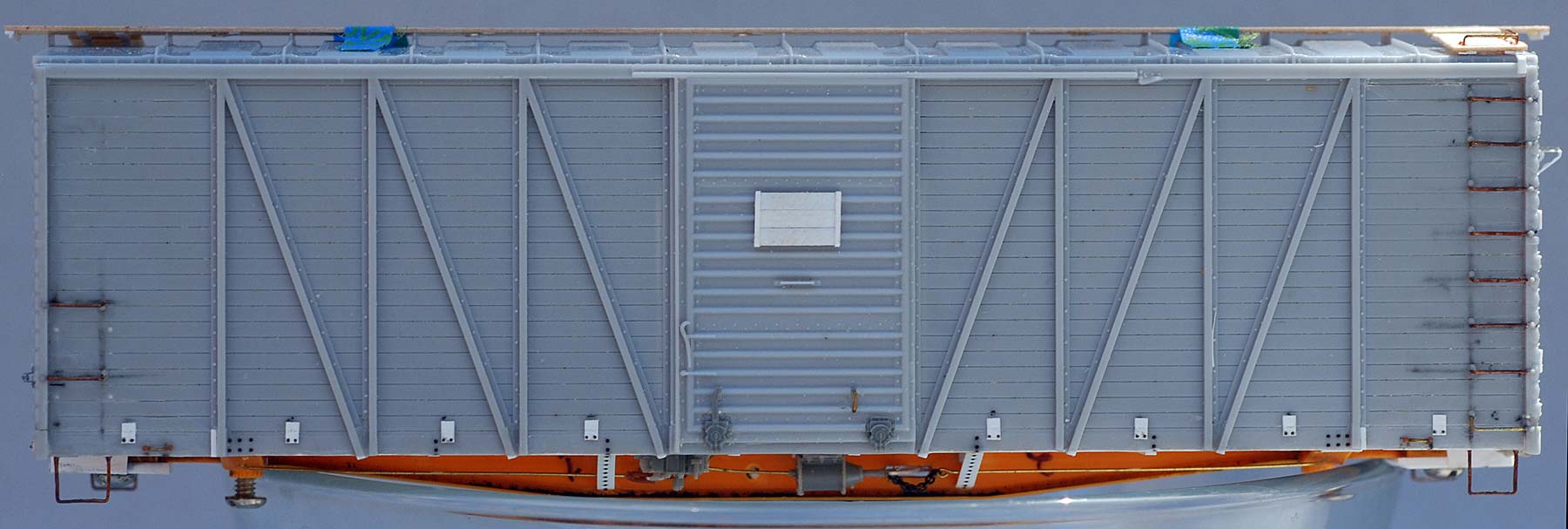
Here’s the car body with he final details in place. In part two I scratch built the placard boards for these cars. I finished these by wrapping the 0.005-inch styrene the frame around the edges and gluing these down on the back of each part, thus creating a sharp frame edge. The MKT prototype placard board frames did not have visible rivets or bolts, so I left them off the frame.
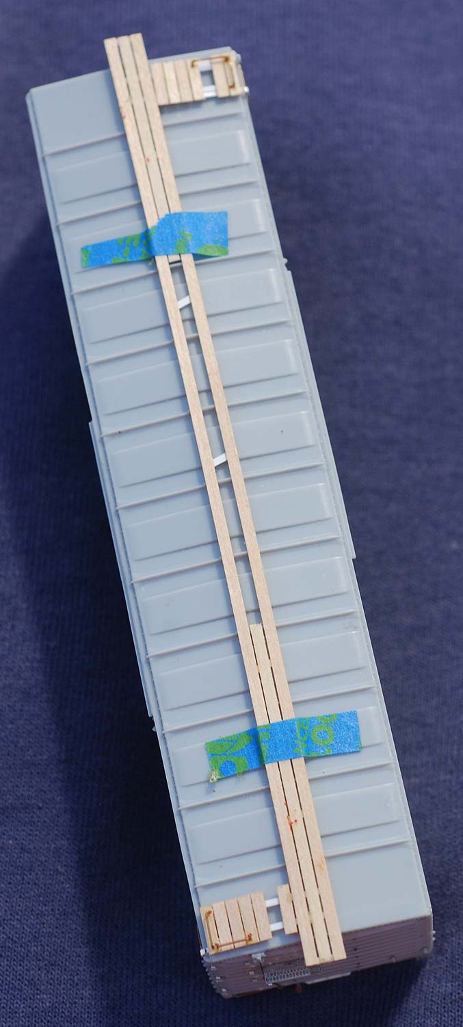
Where appropriate and the mood strikes me, I use Mt. Albert Scale Lumber 2×6 (#MA110P12) to fabricate wood running boards. I leave gaps for replacement boards, as seen in the above image.
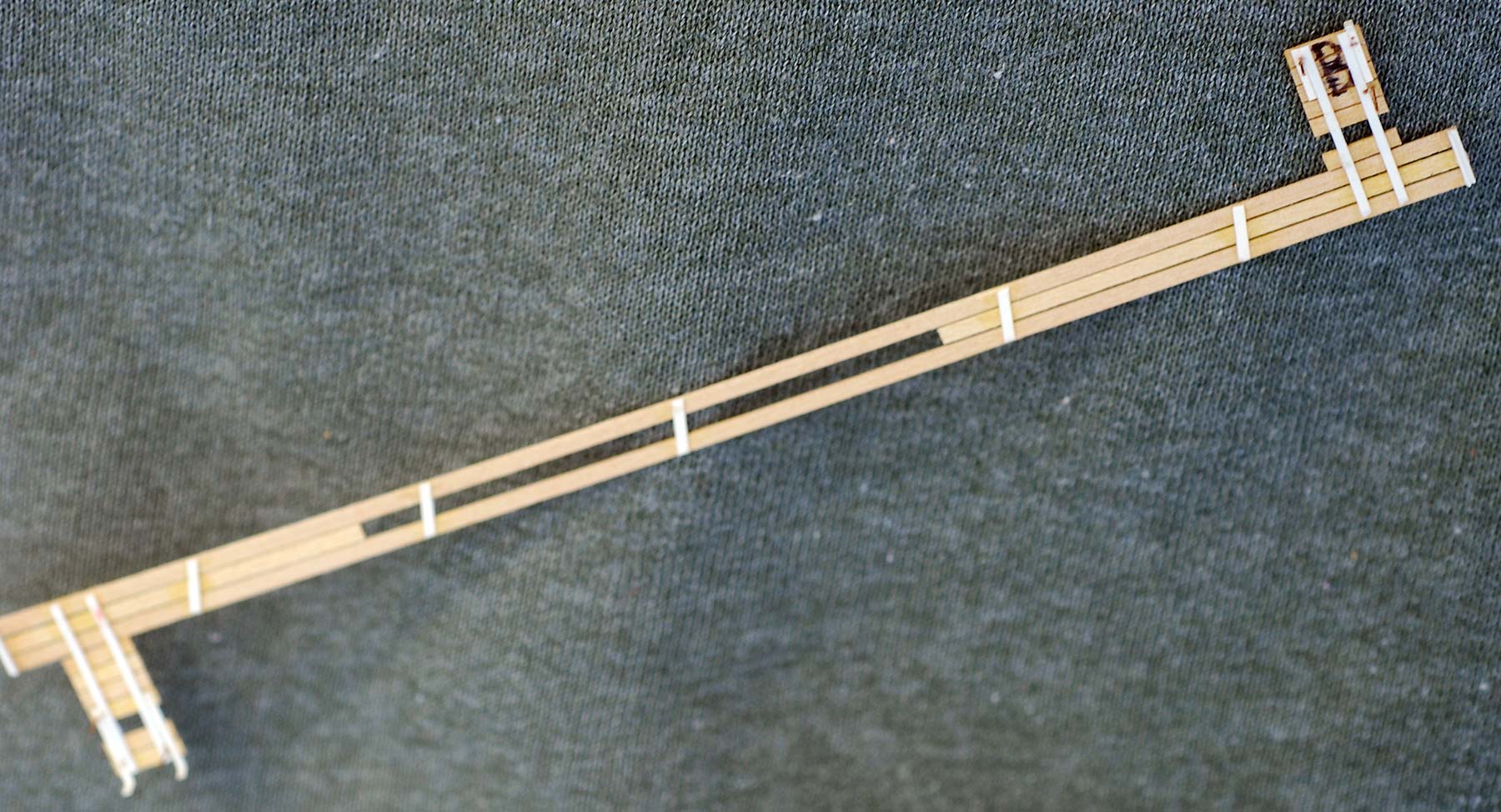
Strips of 0.005-inch styrene hold the structure together so it can be installed after the model is media blasted and washed thoroughly. I mark one end with a “B” to make final assembly easier.

As the close-up photos show I use the grab iron legs on the running board latitudinal as indexing points to install the running board system, centered side-to-side and end-to-end.

I do this by taping the running board assembly to the model, making sure it is located exactly where I want it.
Having previously drilled the latitudinals for the corner grabs, I drill through these into the roof. Then I remove the roof and attach the corner grabs using my favored Duro CA.
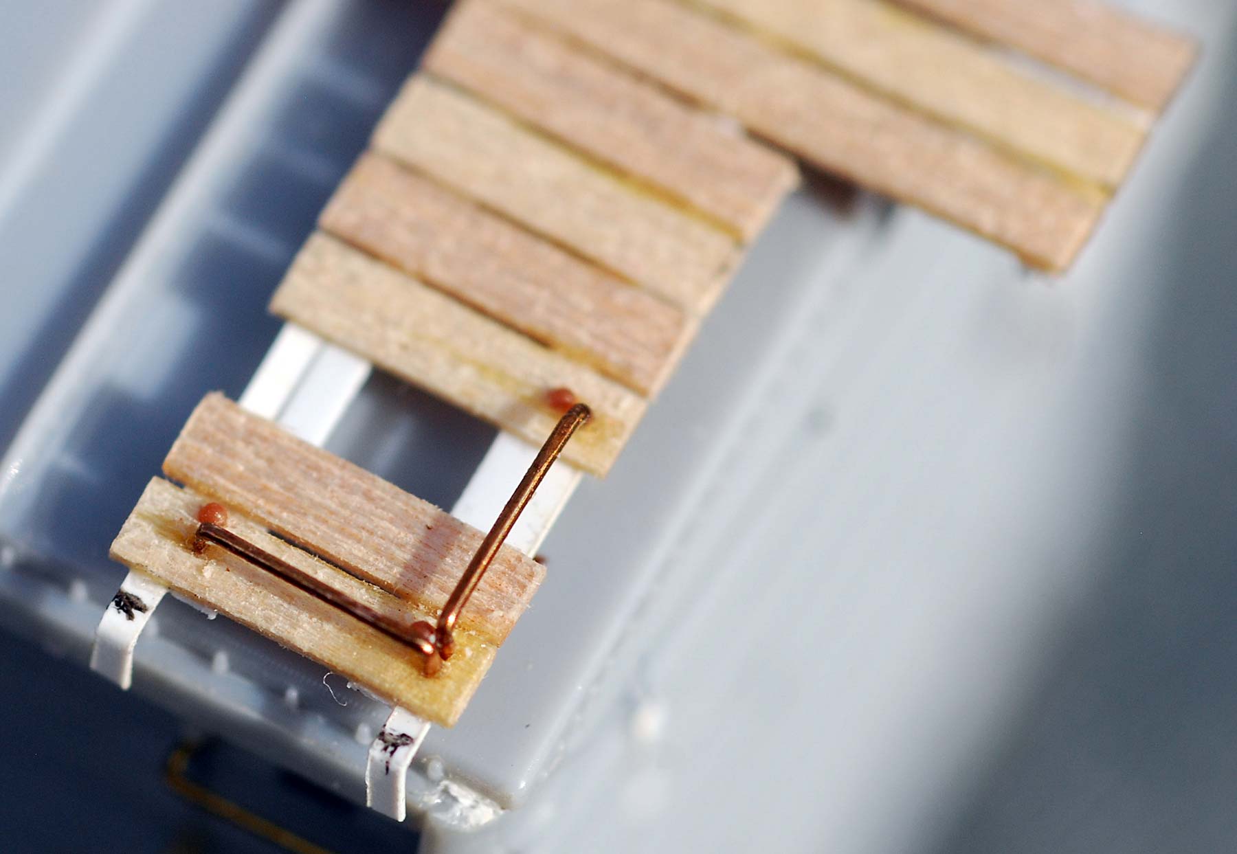
One of the interesting small details of these cars is the corner safety grabs, which were made up of two conventional straight grabs. Again, in the Sloan Yellow scheme this detail will be easier to see so I modeled it. Usually when indexing the running board system to the roof I only leave one leg of the corner grab in place but this time I left two legs on each end uncut. While this indexing technique may seem like a lot of extra work, for me the ready to install running boards will now literally snap into place. It is worth the effort!

We close out this piece with a look at three similar boxcars that are now ready to be media blasted, washed, and painted. From top to bottom, these are InterMountain War Emergency boxcar kits detailed to follow C&NW, M-K-T, and Wabash prototypes.

Here’s are the car ends for a comparison of the details. From left to right, Wabash, M-K-T, and C&NW. The image also illustrates the shortened height of the M-K-T end compared to the unaltered car ends.
Here are links to the previous blog posts covering the MKT boxcar project.
I send a very special thank you to Gene Deimling for his help in funneling information to me about these cars including a PDF of the September 2010 article from the M-K-T historical magazine The Katy Flyer.
Many thanks to Bill Welch for sharing his progress on the MKT boxcar and related projects. His tips and techniques inspire us to open a kit and start building something!
Questions and comments can be posted below. Please follow the instructions so your comment can be posted. All comments are reviewed and approved before they appear. To subscribe to this blog, add your email address to the function at the bottom of the right column on the main page. Share the blog link with other model railroaders.