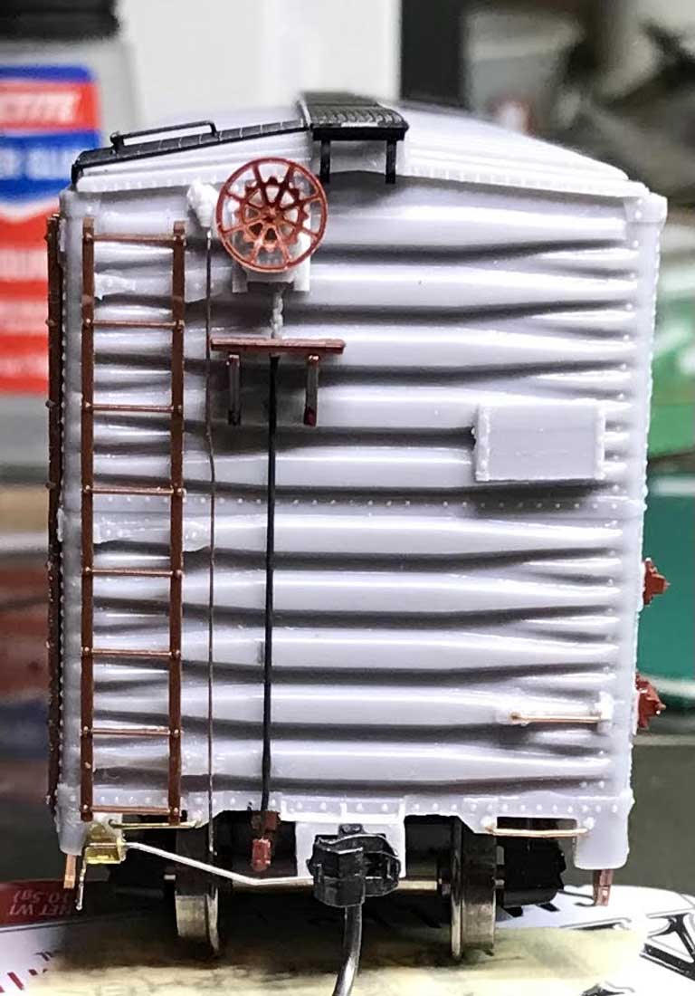
Here’s the fourth feature for the Jerry Hamsmith group kit build of the HO scale Missouri Pacific resin box car.
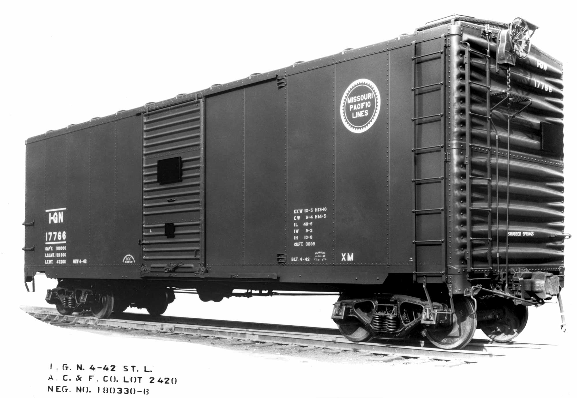
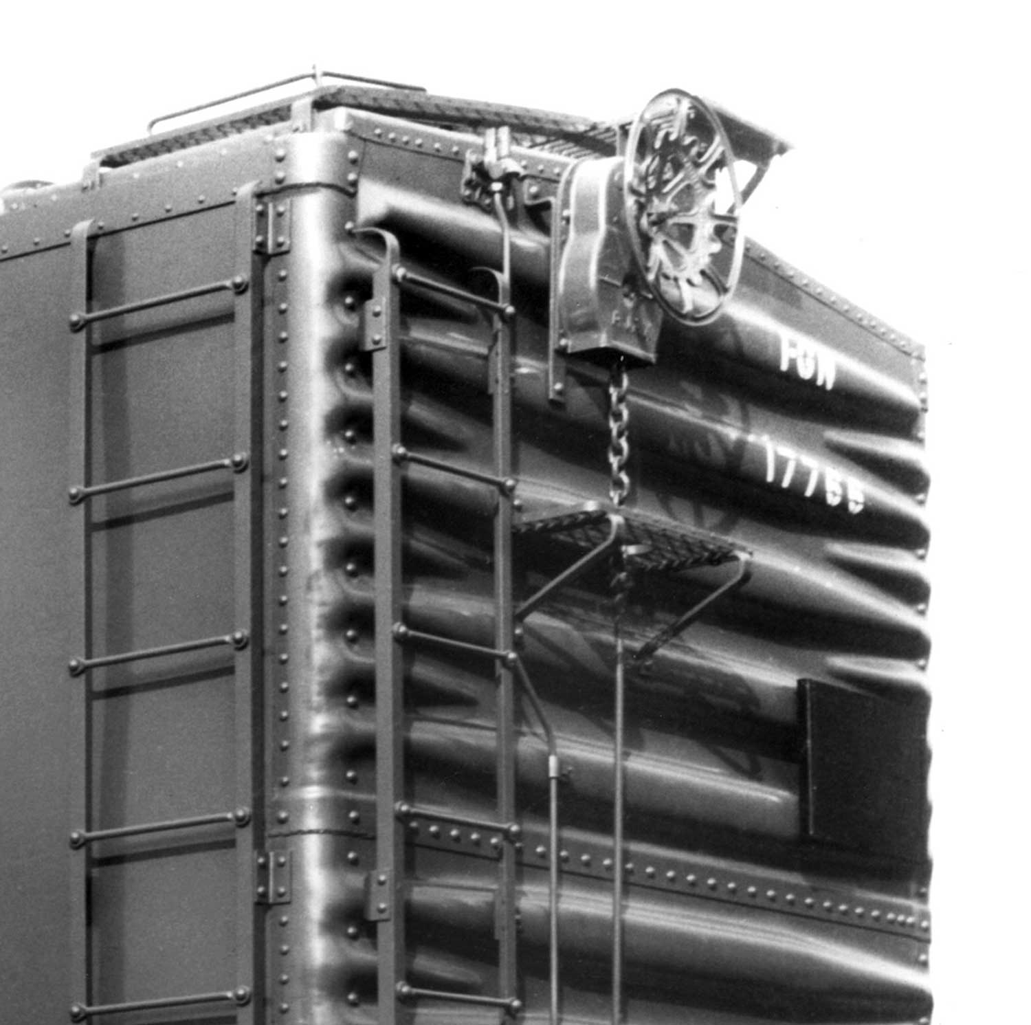
The above builder photo gives an excellent view of the B end detail for these cars. It clearly shows the original tack and route board color was black. Note the very high position of the hand brake. This image guides the next steps for body details with the B end details and running boards.
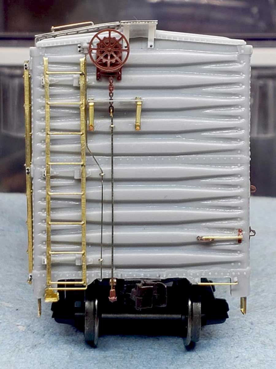
B end details
Some of the brake and retainer detail parts were prepared first. The “chain” has been cut from the Tichy sprue and will be shortened as needed.
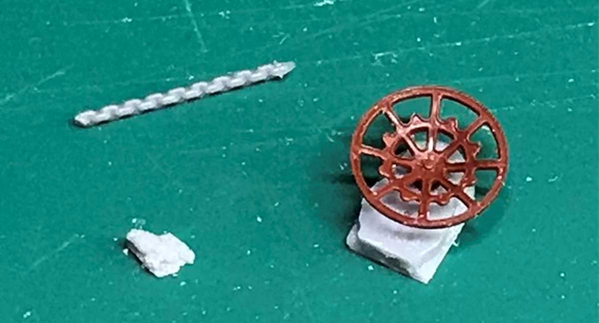
The lower left item is the retainer valve from the resin kit parts. The brake housing itself is also from the resin kit parts and a Kadee Ajax brake wheel was attached. Tichy 0.008-inch diameter phosphor bronze wire (PBW) will be used for the retainer line and 0.0125-inch wire for the brake stem.
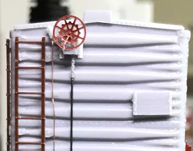
The retainer valve was added first. A scrap piece of 0.020-inch thick styrene was used as a spacer under the resin valve casting. A #78 bit was used to drill a hole just below the casting as an anchor for the 0.008-inch PBW used as the retainer line. A small kink was purposely added to the line just below where the brake step location to allow the line to exit under the car interior to the grab iron. The wire was cut to length and cemented into the hole at the top and under the edge of the car at the bottom.
Once the retainer line was in place, the hand brake housing was added to the car end. The placement was determined by consulting the prototype photos and then drawing a vertical line on the car end to where the bellcrank would be located, just left of the coupler.

The kit resin parts include the straps used under the hand brake housing. I substituted styrene strips for those resin parts and glued them to the end. Then the hand brake was glued to the straps along with the brake wheel.
A bellcrank can be seen at the bottom of the brake stem in the above image. This detail is a Cal-Scale plastic part. A small hole for the brake stem was drilled into the bellcrank before attaching it to the car. A #74 bit was used to drill a hole into the brake step rib in line with the bellcrank. When the parts were aligned with the brake housing, they were glued into in place.
The proper height of the brake step was determined from prototype pictures. It seems to be along the third rib from the top of the car end. I installed the step and supports based on the prototype.
The Tichy chain was glued under the hand brake housing and trimmed off at the hole. The brake stem section was measured and glued into the hole and the bellcrank. The brake stem is 0.0125-inch PBW. Note on the prototype, the chain and stem are slightly offset from the middle of the brake step.

Chris Vanko applied a Precision Scale retainer valve and 0.008-inch PBW for the retainer line. He decided to use the hand brake housing and brake wheel from the Tichy parts sprue provided in the kit. The chain is 40 link/inch from A-Line, and the rod is 0.0125-inch PBW. His brake platform is the kit provided Plano Model Products part and the supports are from the Tichy sprue.
Ed Rethwisch used the kit resin retainer valve and installed 0.006-inch wire for the retainer line. He also used the Plano brake step but bent his own supports. The Ajax power hand brake housing and wheel are both Kadee parts.
Running boards
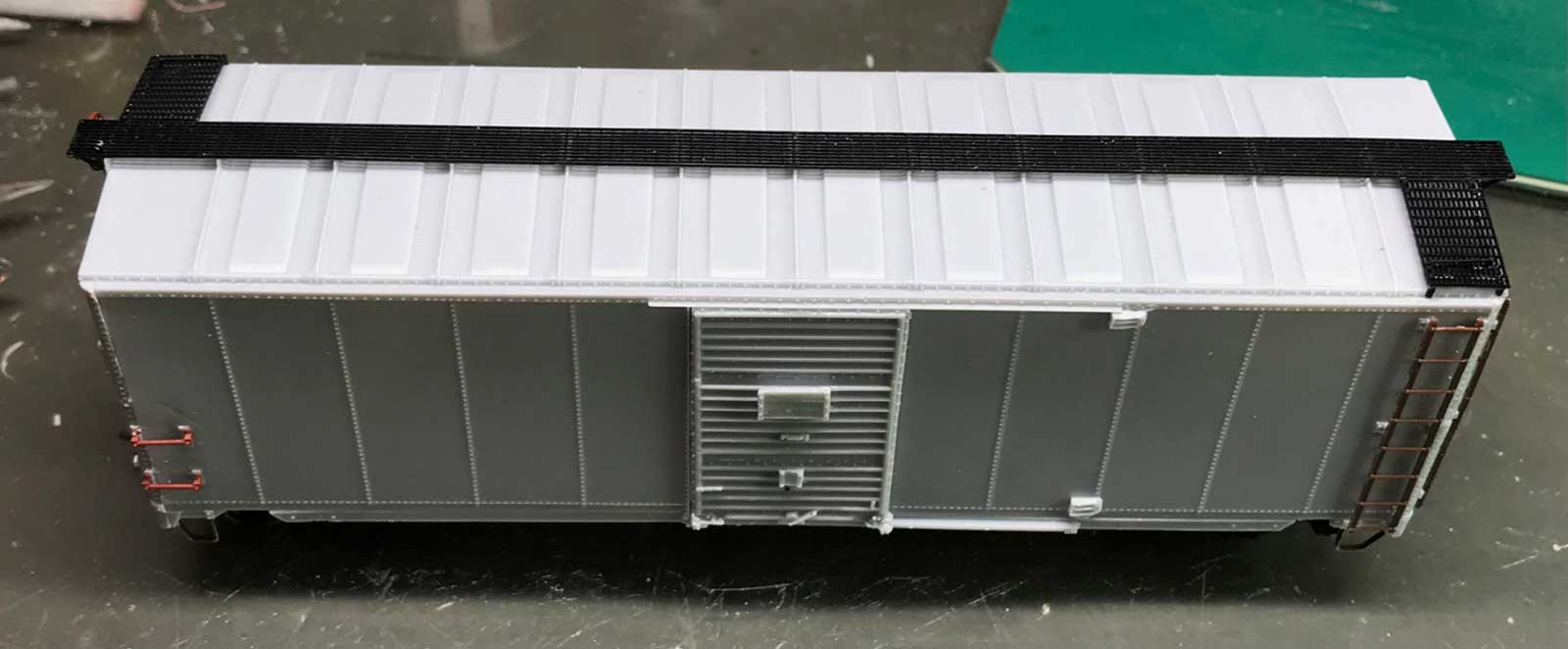
For the running board, I used a Kadee Apex running board assembly (#2002 Black). One of the kit’s cast supports for the running board pieces broke off of my car. I filed the area level then added a cut down 0.020 x 0.040-inch styrene piece to replace it. Once dried, I filed it to match the level. I removed all the nubs from the Kadee part and then attached it with Canopy glue.
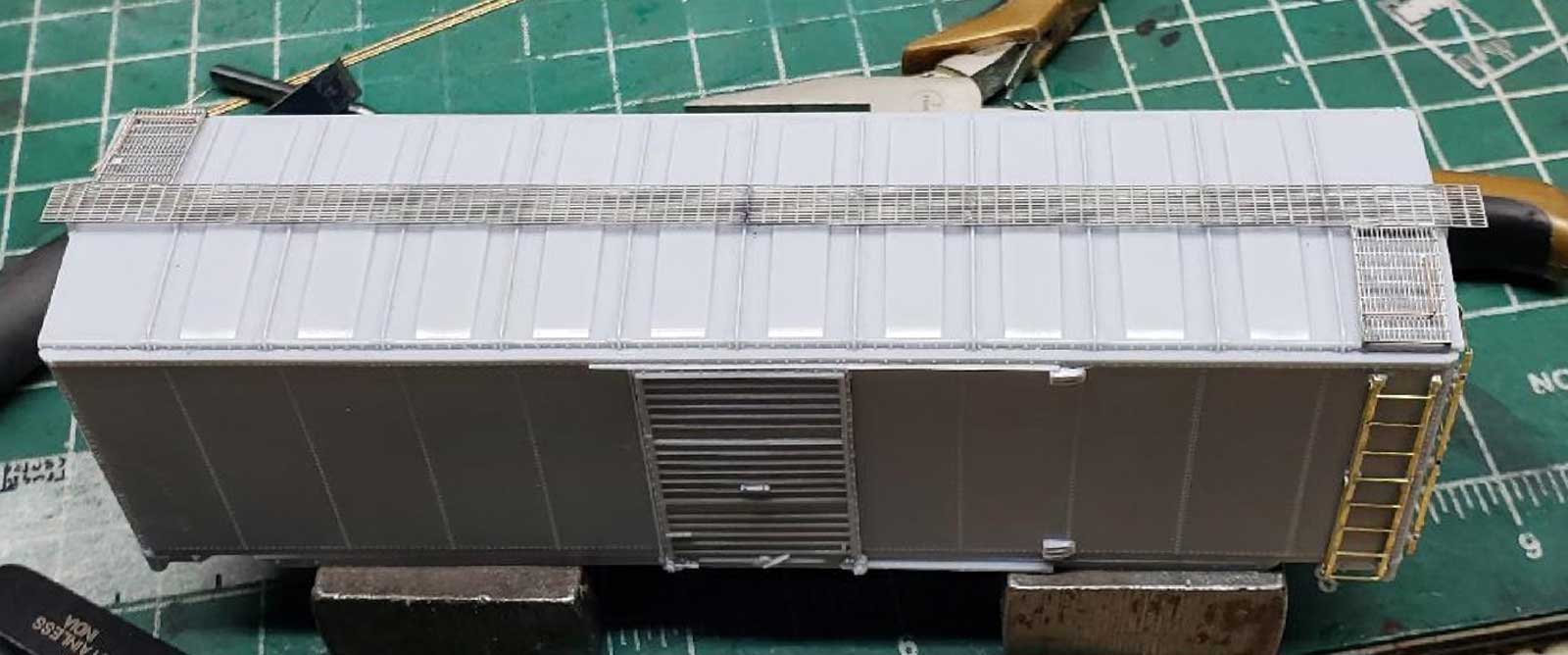
Ed Rethwisch used the kit provided Plano etched metal running board. The kit includes the longitudinal board, two lateral boards, and the supports for the laterals. He soldered the sections of the running board together and then used Canopy glue to attach the assembly to the roof. The corner grabs were made from 0.010-inch PBW and inserted into pre-drilled holes.
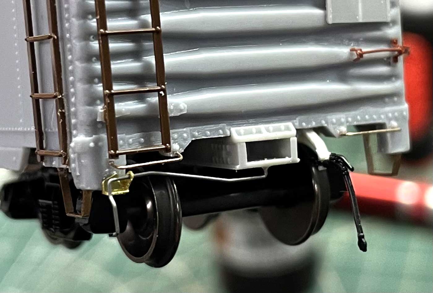
Cut levers
The remaining car body details are the cut lever supports, the cut levers, and the air hoses and their brackets. These parts are somewhat fragile and could be left off until after the model is painted.
I decide installed them now and used the Yarmouth Model Works support brackets (#507). I formed the cut levers from 0.010-inch PBW. I do not add the angle cock or air hoses to my builds. My cars are used in operating sessions.
Chris Vanko also used the Yarmouth cut lever supports and created his own cut levers. He added slightly modified Moloco Trains air hose and angle cock details (HE-0308).
The last installment will cover the painting, application of decals, and weathering of our box car builds.
A group of modelers (Ed Rethwisch, Chris Vanko, Bob Hanmer, Allen DeBraal, Brad Hanner, and myself) have been progressing on the recently released Resin Car Works Kit 8.05, a Missouri Pacific 1942 ACF boxcar. Here are links to the previous blog posts.
- Part one summarized the background and first steps
- Part two focused on the sill steps and brake appliances
- Part three covered car body details
We hope these step by step blog posts encourages modelers to build any resin kit and, specifically, to aid in building this RCW kit.
Many thanks to Jerry Hamsmith and his group for sharing their resin freight car kit building tips. We look forward to finishing these models!
Subscribe to the Resin Car Works blog so you don’t miss inspirational modeling and new model announcements. Add your email address to the Subscribe function at the bottom of the page.
Questions and comments can be posted below. Please follow the instructions so your comment can be posted. All comments are reviewed and approved before they appear. Share the blog link with other model railroaders.