Bill Welch keeps our heads spinning with his modeling project shares on discussion lists. Here are his notes and photos covering some gondola details.
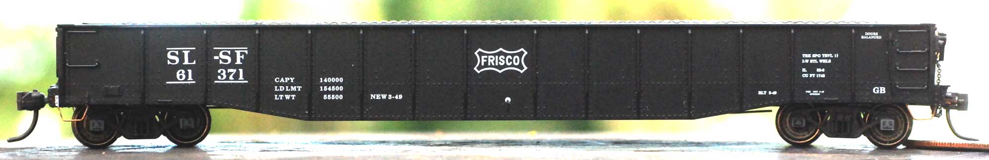
Ever since I saw the Greenville designed 52-foot mill gondola in Railway Prototype Cyclopedia (RPCyc) Volume #3, I have intended to build the SL-SF version discussed in the article. Since the FRISCO served Birmingham, Alabama, I consider it an honorary Ya’ll Road.
I had already built the beautiful Sunshine Models resin gondola kit for the Nickel Plate Road and like the lines and proportions of this workhorse. First thing I did after reading the article was to acquire an undecorated Life-Like Proto2000 kit and then let it sit around for years.
One of the things that stalled me was fabricating the interesting Pullman ends. My experience building the Sunshine kit taught me how to use a form and thin aluminum sheet to press a complex shape, like a corrugated end. What I needed was a correct, or nearly correct, form.
Another thing that stalled me was how to make the lading anchors on the top of the bulb angle. My friends John Golden and Justin May had made some by squeezing thin wire between two pieces of corrugated styrene siding. Their final rippled effect looked great, but I could not get this approach to work for me.

A few years ago, Tangent Scale Models produced HO scale 52-foot gondolas of Bethlehem Steel prototypes. Some of which had photo etched (PE) parts for the lading anchors. By the time I realized these parts were available separately, they were sold out. However, I mentioned these parts to my friend Bill Pardie and he had two pair of the lading anchors. He did not think he would ever use them so he gave them to me. Wow! These parts are occasionally available from Tangent.
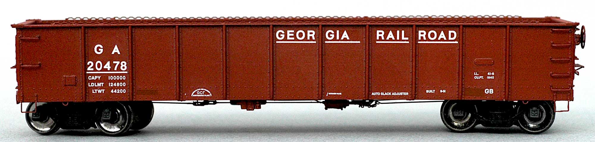
I installed a pair on an Accurail 40-foot AAR gondola to model a Georgia prototype. The lading anchor parts were shortened to fit the model.
Sometime afterwards, I visited a train store that had a fair inventory of kits purchased from retailers going out of business. I found two Proto2000 52-foot gondolas factory painted for the FRISCO, one black and one freight car red. I bought them both and decided to modify the black one first.
I note that when it comes to modeling, I have become a sort of “Doomsday Prepper” because many kits and parts sometimes do not stick around long, When the etched lading anchor parts again became available from Tangent, I ordered two packets not realizing there are two pair of pairs in each package. I think I am now set for life with lading anchors.
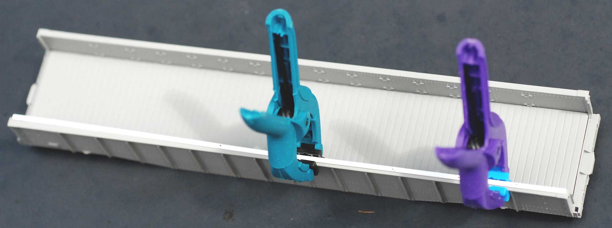
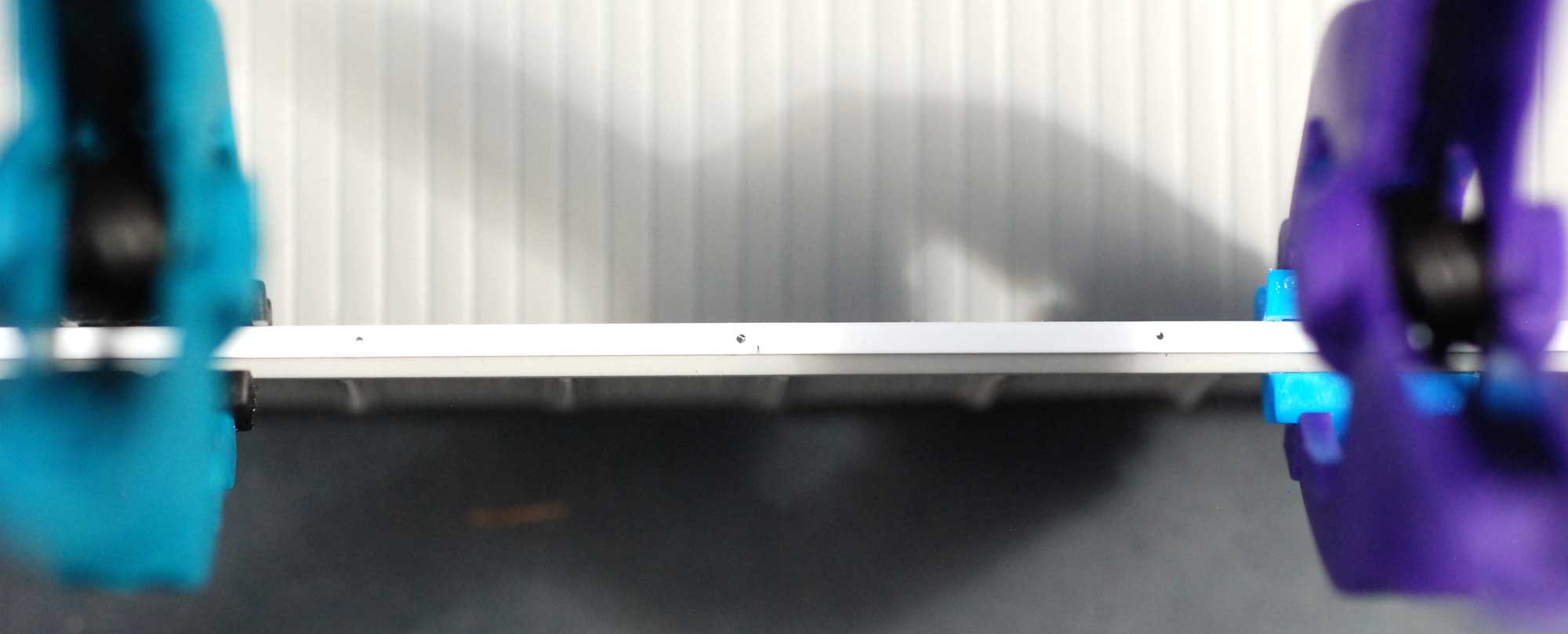
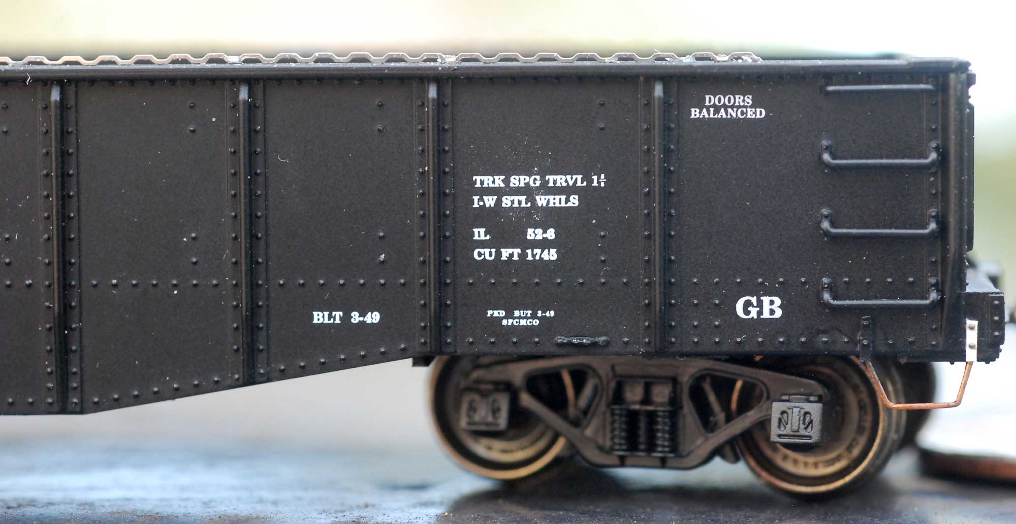
I felt I did a mediocre job installing the lading anchors on my Georgia gondola. I decided to up my game for the next attempt. I began by taking a section of Evergreen 0.060-inch angle styrene (part #291) and marked holes for the lading anchor. This would be my drilling template. These holes on the top of the bulb angle needed to be through the car side so I made sure the holes in my template just inside where the angle joined, as you can see in the image above.
After making a dimple for the drill location, I used a #79 bit to drill a shallow hole. I followed with a #78 bit to make a deeper hole. I found this was the perfect size to accommodate the PE’s mounting tab.
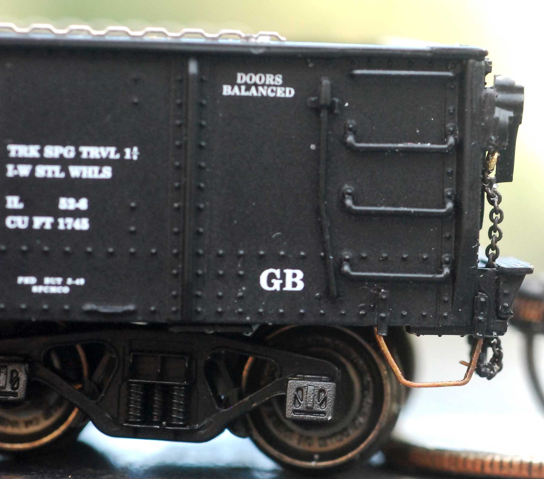
Once in place I used Cyanoacrylate (CA) to secure each strip. For whatever reason one side went on straighter, but I am happy, nonetheless.
Although I had a plan on forming the new ends, Tangent once again stepped in with ends from one of their gondola models. I purchased the parts from Dave Lehlbach at the 2019 St. Louis RPM.

Adapting the Tangent ends was easy. I added a piece of 0.010 x 0.060 -inch styrene to the top of the ends as a bulb angle.
I tried to cut off the styrene sill steps to preserve the riveted attachment strap, but some came off because they were not effectively glued onto the model. No big deal. I simply used some 0.005-inch thick strips and harvested rivets from an Athearn boxcar body for the attachment bolts. The new sill steps were formed from A-Line type A steps by heating and shaping with pliers.
Before calling the detailing work complete, I thought better check on the correct prototype floor. It’ a good thing I emailed Ed Hawkins, as he told me these cars had welded steel floors. He included these details about how the floor was welded:
the welded floor for the 1949 cars (61000-61300) having 15 separate sheets, 5/16-inch thick steel plate, butt-welded crosswise, and arranged per the following widths starting at either end. The length of each floor sheet was approximately 9-foot, 6-inches to fit snugly between the sides, where continuous welds formed solid joints.
4-foot, 11 5/8-inches – 3-foot, 10-inches – 3-foot, 3-inches – 3-foot, 1 3/4-inches (four sheets in a row of this width) – 3-foot, 10-inches (middle of car) – 3-foot, 1 3/4-inches (four sheets in a row) – 3-foot, 3-inches – 3-foot, 10-inches – 4-foot, 11 5/8-inches
. . .each floor sheet was bent slightly upward at the ends with a curved lip where it met the sides. The curved edge was such that water didn’t collect at a corner weld at the sides, which would have caused corrosion and weaken the joint. With the curved lips, water would have gravitated towards the middle. I’m unsure about any drainage provisions for the welded steel floor.
The 14 welds were directly above each bolster (welded not centered), six crossbearers, and six crossties. The welds above the crossties were centered above the flanges of the pressed-steel channels having 2 1/2-inch flanges and approximately 9-inches high. The crossbearers were comprised of three steel plates welded top & bottom to form the shape of an I-beam.
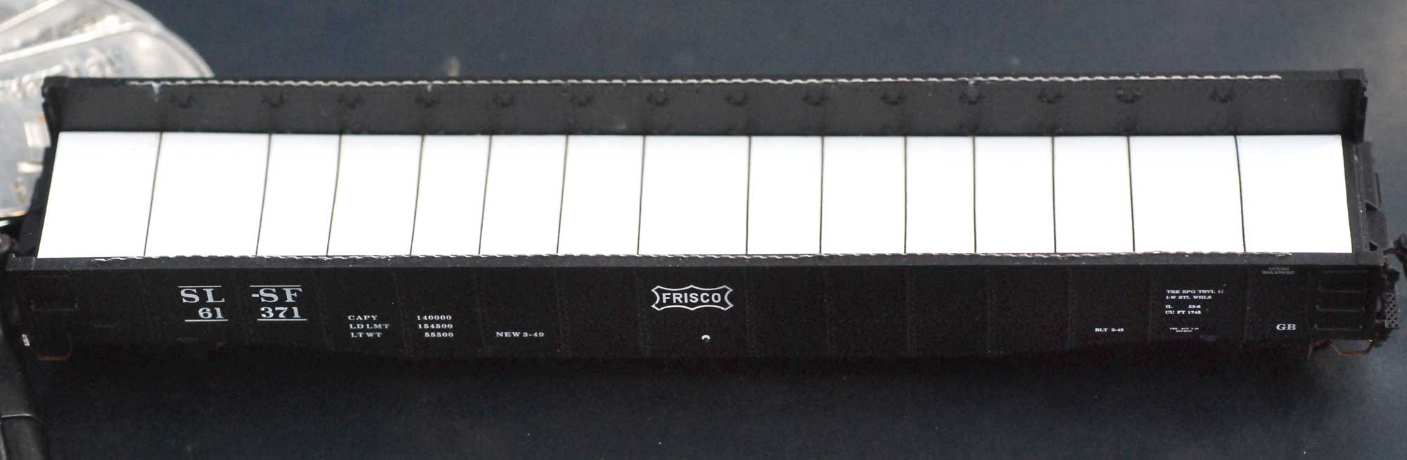
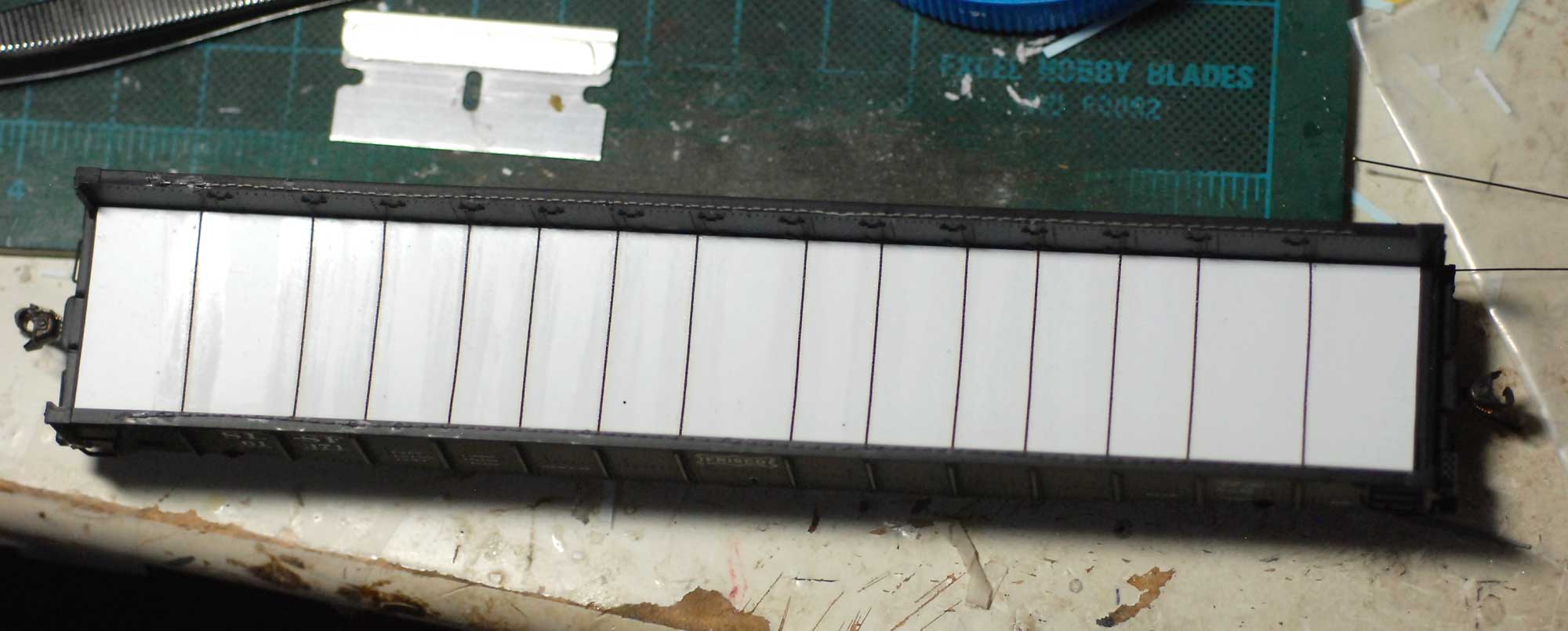
It seems I needed to make a new floor. I started by measuring the interior dimensions with my recently purchased Mitutoyo Digimatic caliper and transferring the dimensions to 0.005-inch thick sheet styrene. I drew feint pencil marks at the appropriate increments for the weld joints. I then brushed on Pledge Future/Revive It Floor Gloss (whatever they call that clear acrylic floor coating now) to provide a base for the mid-size Archer Aircraft Panel Line decals for the weld beads. My pencil marks helped me locate where to apply these and keep them straight. After settling and setting these with blue and red Microscale decal solutions, I brushed on two more coats of the floor gloss to protect them.
Because the floor was welded along the inside of the side, there are fewer rivets along the side panels. Frankly, I am not sure if I will try to remove these from the model. I think when I’m unsure how to proceed, putting a project aside until I am thinking clearer is always a good idea. Since this one has taken me 20 plus years to get going, obviously I am not in a hurry.
Many thanks to Bill Welch for sharing his work on these gondola details.
Questions and comments can be posted below. Please follow the instructions so your comment can be posted. All comments are reviewed and approved before they appear. To subscribe to this blog, add your email address to the function at the bottom of the right column on the main page. Share the blog link with other model railroaders.
I should add that I will need to change the car number and more or less stalled on this too. If I can find matching numeral decals, this may mean painting over a number or two and then adding the decals. If I cannot find matching numerals, I will need to replace the entire car number to match the cars with the lading anchors.
Awesome Bill keep up the good work.