George Toman sent details on one of his recent model builds. Here he is with the details and photos!
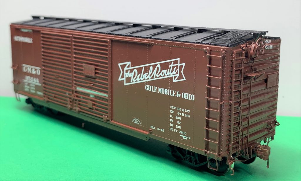
One car that caught my attention was a Gulf, Mobile and Ohio 40-foot automobile boxcar. The prototypes were built in 1942 by American Car & Foundry (Lot # 2345), and had a 10-foot, 6-inch interior height.
Speedwitch Media once offered a kit that included the proper car ends, doors, and decals. A Branchline postwar 7-foot door opening boxcar kit was recommended as a starting point. I was fortunate to have purchased a kit from Ed Hawkins that also included the body. Ed also directed me to the National Museum of Transportation to purchase copies of the General Arrangement drawings to help build an accurate model.
I purchased GM&O drawings from the National Museum of Transportation Collection. These are in the ACF Lot 2345 Drawings. General Arrangement 61-1924 GM&O and Brake Arrangement 61-1925 GM&O were very helpful for the details on this model.
The GM&O 35200-35249 series of cars were equipped with Evans auto loaders with chain tubes. They had Apex Tri-loc running boards and brake steps, and Equipco hand brakes. Trucks were spring plankless cast sideframes. As built, they were painted freight car red with black roofs, and lettered in “The Rebel Route” scheme. In the 1950’s these cars were repainted. They now had black ends with the black roofs, and “The Rebel Route” banner was dropped.

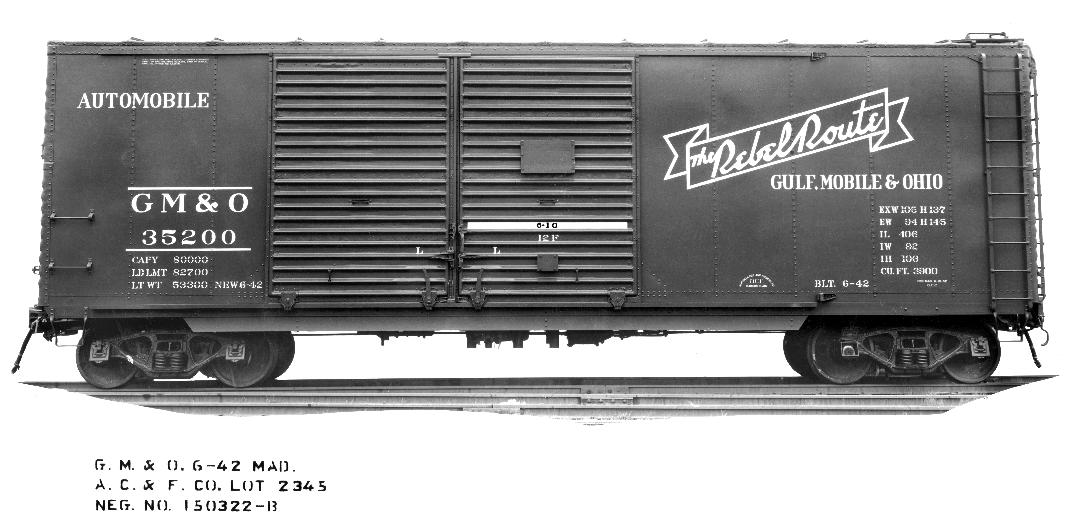
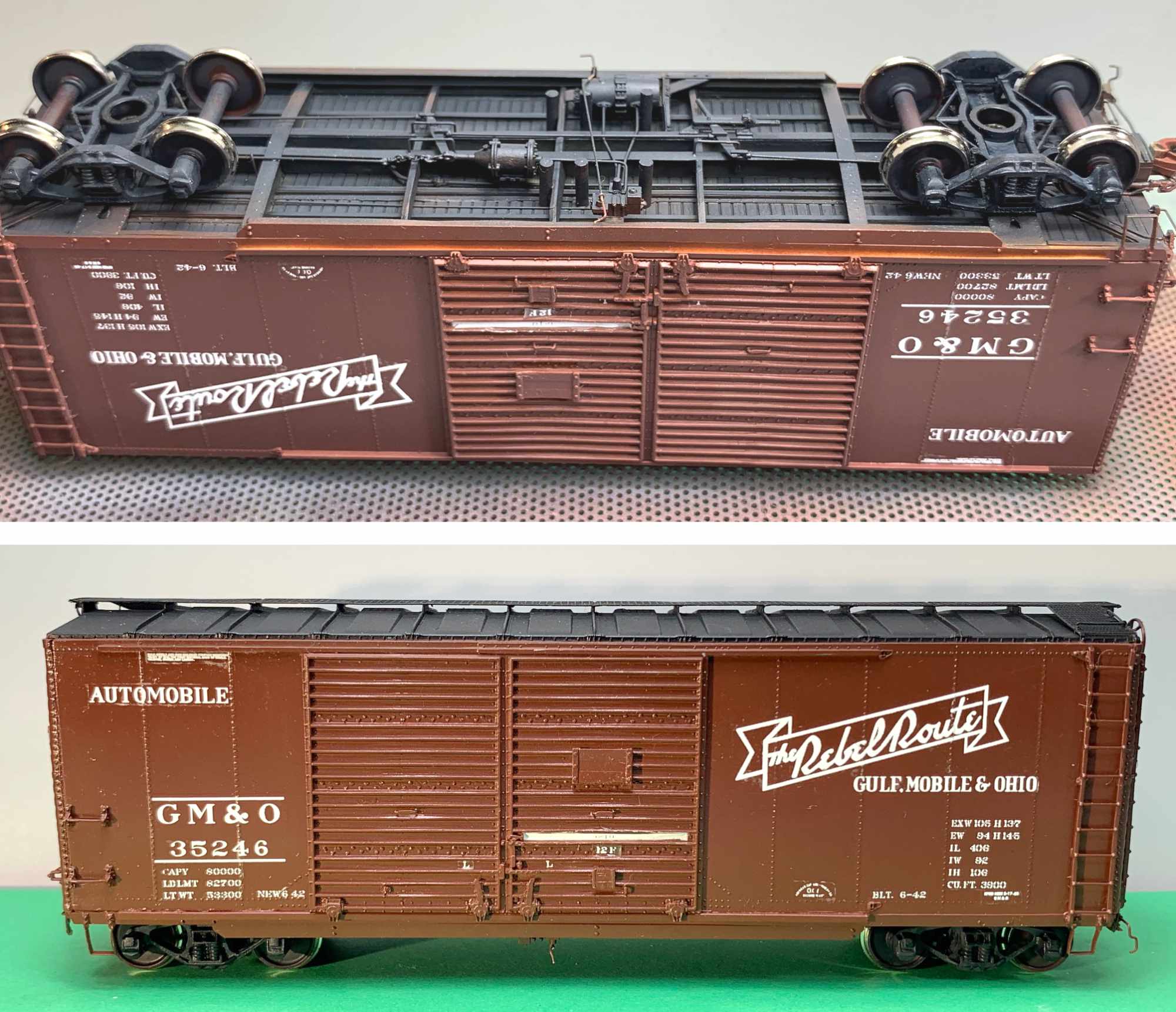
An unusual feature of these cars was the use of ten rung ladders. If you look closely at the B end photo above, you can see that the inboard stile was a flat bar that was formed to shape to the corrugations for mounting. I have circled these in yellow. (Click on any photo here to review a larger size.)
As I compared the Branchline model to the prototype drawings, I found the underframe was not correct. The GM&O had stamped angle corner supports and not the floor stringers running to the ends. With the information at hand, I decided to scratch build a new underframe from styrene.
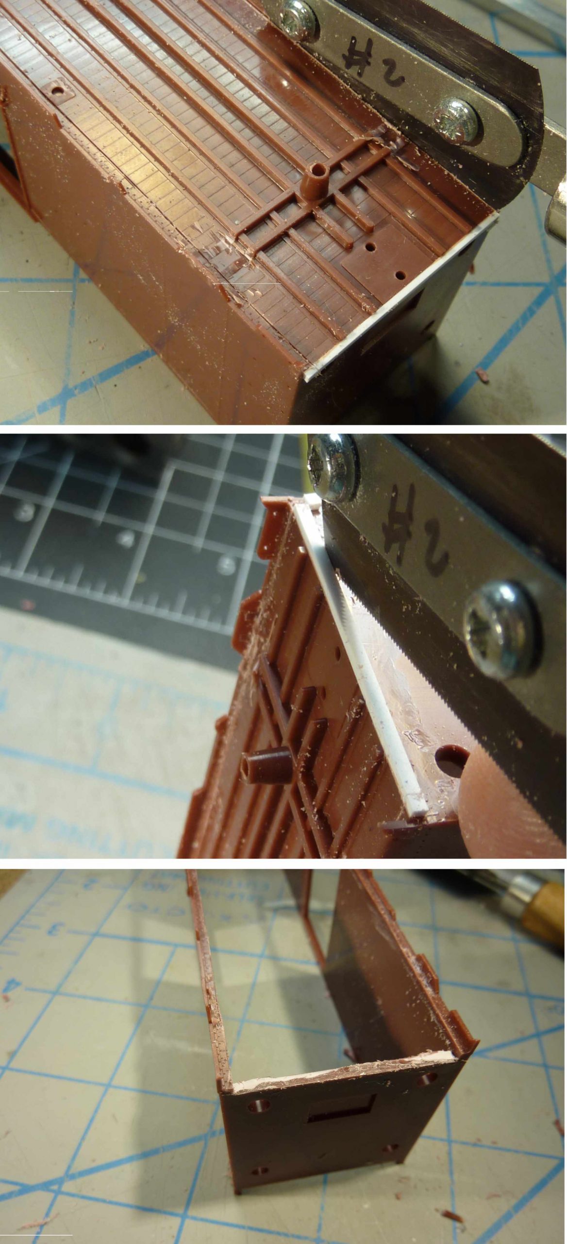
The above photos illustrate my process. I cut out the floor of the Branchline model with an UMM micro saw. I glued a piece of styrene on the end as a cutting guide for the saw.

A new 0.060-inch thick styrene scribed floor was cut to size and fit into the carbody. I saved and reused the bolster center piece from the removed floor as these were used with the old Branchline supplied bolsters. Styrene strips were glued to the underside of the bolster to provide the correct car height.
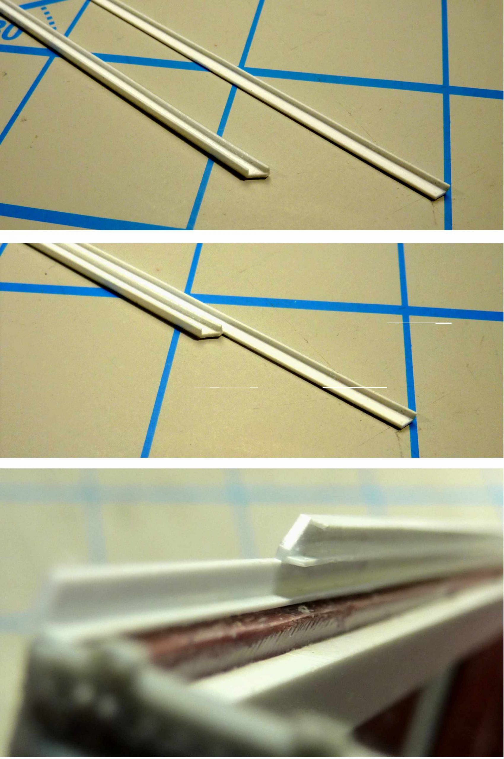
I crafted new side sills from Evergreen styrene to run the length of the car, as measured from the General Arrangement. The side sill is constructed from making an L running the length of the car and a C that runs between the bolsters. The last photo above shows the side sills glued in place. However, they were glued after the lower door track was fabricated and installed.
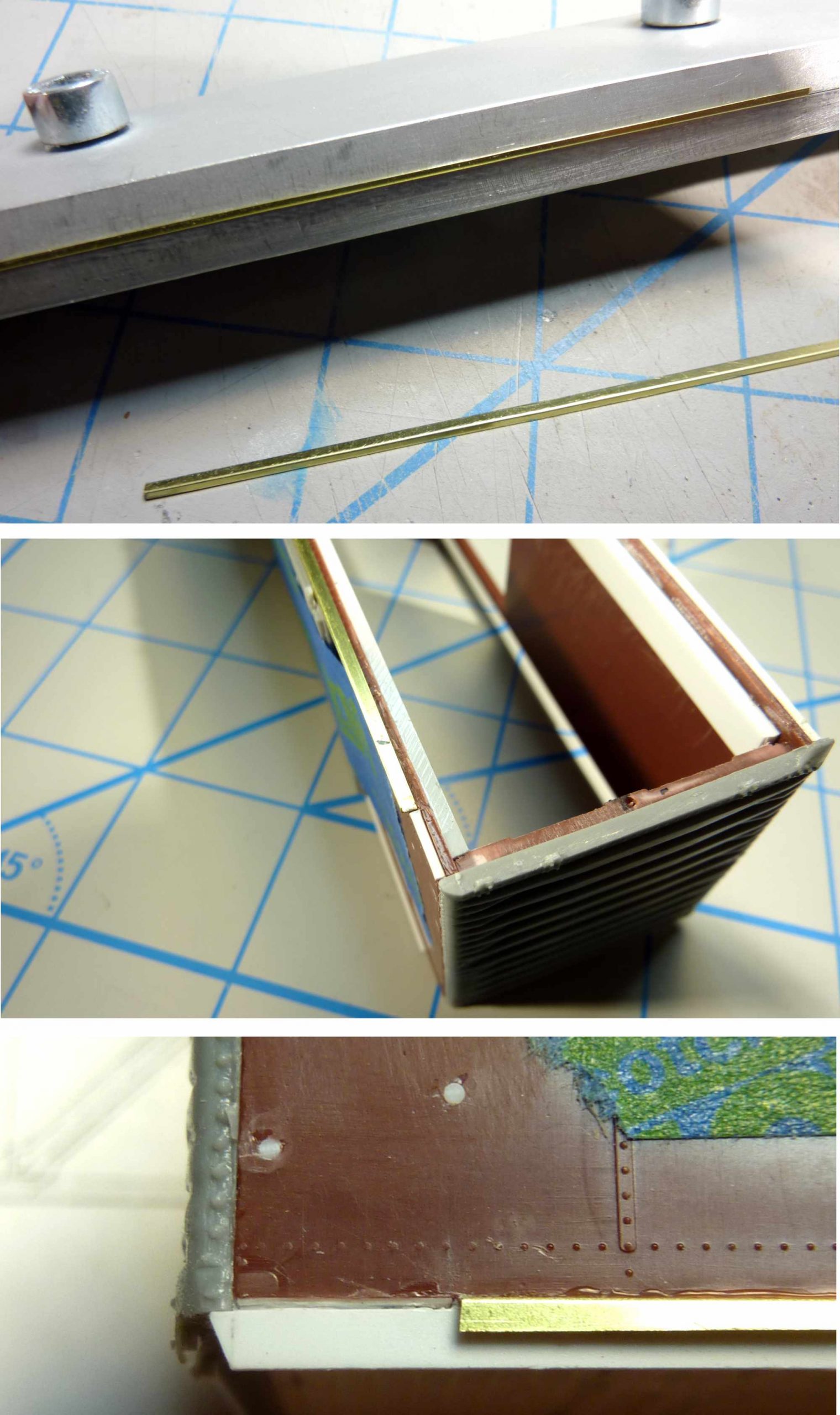
I wanted to accurately model the long door tracks for the double doors. I fabricated these from 0.005-inch thick brass stock. I cut the brass to width and used a photoetch bending tool to form the L. I was concerned about mounting the lower track, so I made the one leg longer than necessary. This extra width would be sandwiched between the carbody side and the new styrene side sills from the previous step. As the brass is 0.005-inch, I used 0.005-inch thick styrene spacers to keep things in line. The last photo above shows the left side of the sill. You can see the thin spacer between the carbody side and new side sill. It fit between the car end and the brass door track.
I focused on constructing the rest of the underframe next. Using Evergreen styrene, I constructed the center sill and floor stringers using techniques I described in a previous blog post.
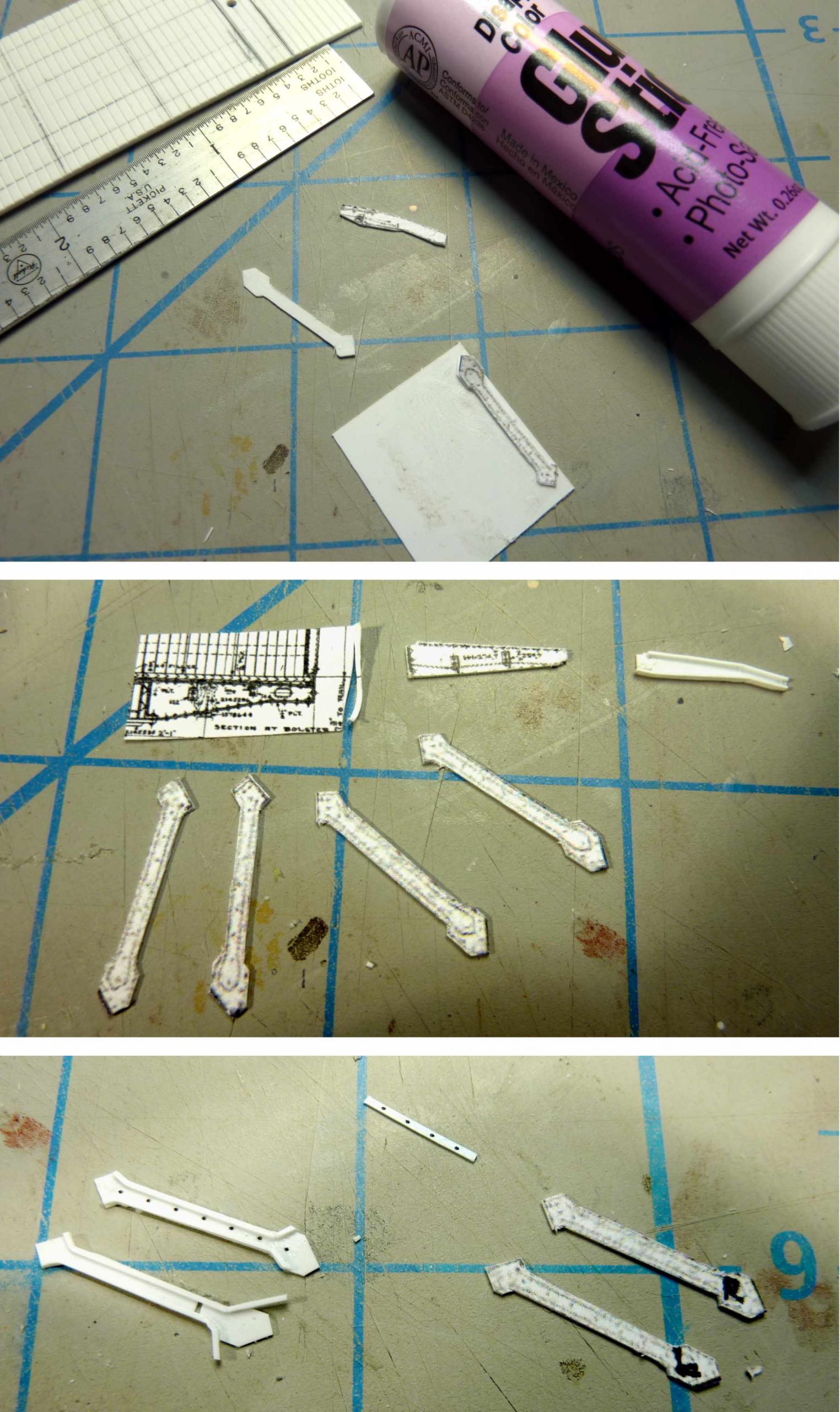
I used a slightly different method for the cross bearers, cross ties, and corner supports. I resized and printed the General Arrangement drawings to HO scale. I cut out the four corner supports, cross bearers, and cross ties from the drawing. I used a glue stick to attach the paper cut outs to the proper size styrene and accurately cut out the parts. The pieces were finished with 0.010-inch thick styrene strips to give them the proper shape and depth. Archer rivets were added as appropriate.
Here’s the completed underframe before adding the brake components. Note the cross bearers and cross ties nest in the side sill. Chain tubes have not been added yet.

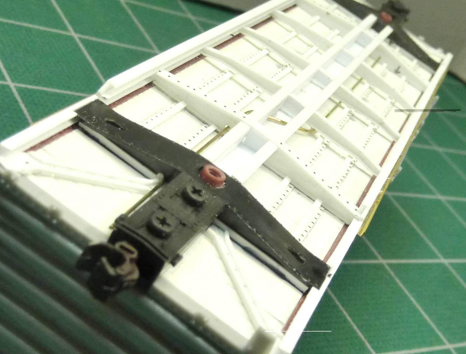
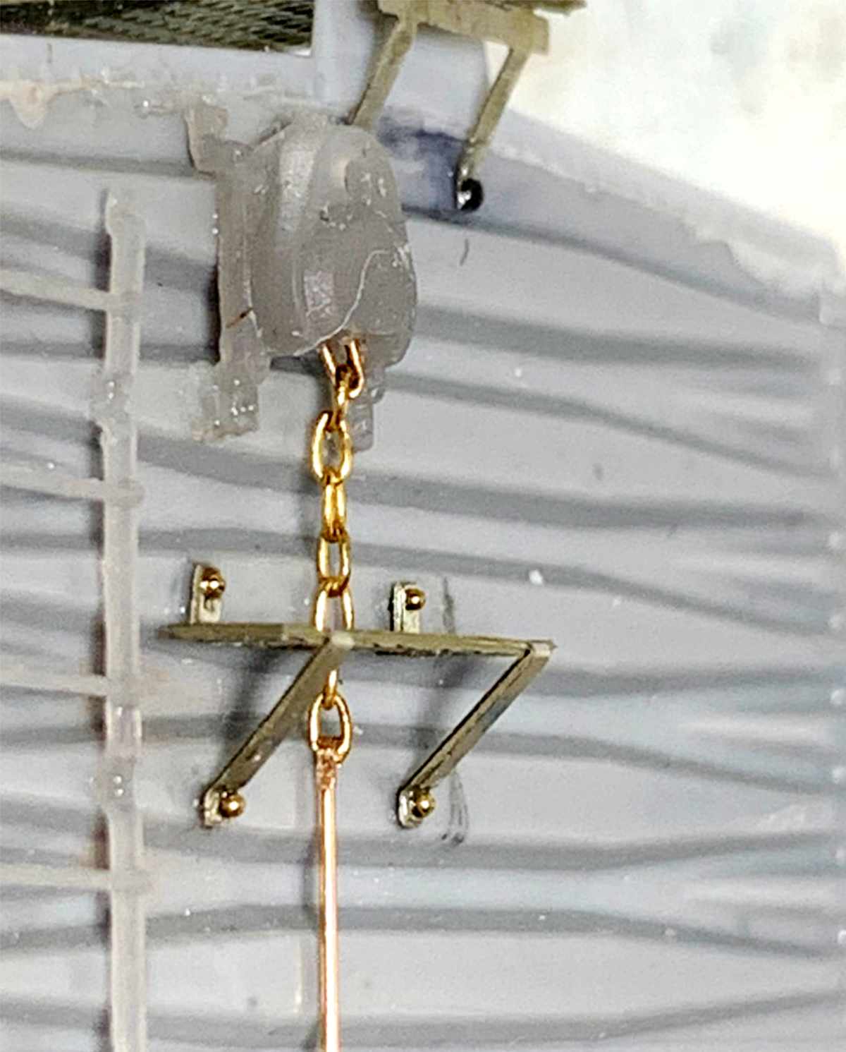
With the underframe complete, I installed Cal Scale AB parts and Tichy wire for the brake components. I followed the brake arrangement drawing for proper placement and to construct the brake cylinder, AB valve, and brake reservoir mounting brackets. Note the chain tubes are in place in the photo above.
I used the Cal Scale part this time as the brake reservoir casting is a better (wider) fit. The Royal F Type slack adjuster is a 3D printed part from Kadwell Mfg Co., via Shapeways.
One thing that really slowed me down with this project were the ten rung ladders. The Speedwitch kit included a resin jig with proper rung spacing, but the instructions called for gluing Tichy ladder rungs to styrene strip ladder stiles. This wasn’t the look I wanted.
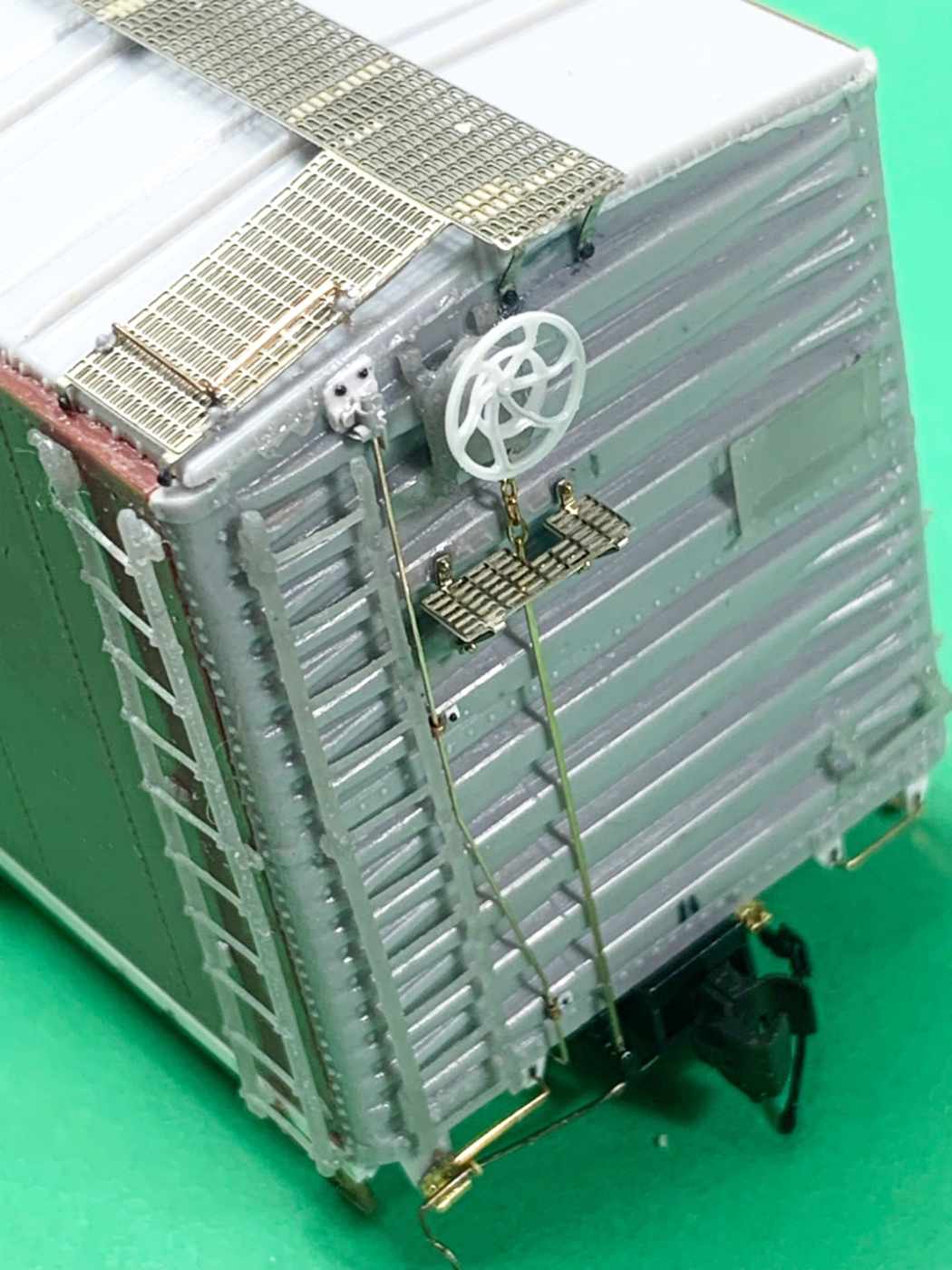
I was going to make my own from brass but got an email from my friend Jim King of Smoky Mountain Model Works. After discussing these unique ladders with Jim, he created accurate 3D printed hardware. He printed ladders, side grabs, end grabs, tack boards, Equipco brake housing, and brake wheel all scaled from the General Arrangement drawings. Jim used an SLA 3D printer with resin that is a bit flexible to reduce rung breakage of the rungs. You can see the results in the photo above. You may contact Jim at his website and request these if interested. Smoky Mountain Model Works. Contact details are at the bottom of that page.
I elected not to use the 3D printed brake step and relief valve. In the detail photo above, you can see the small brass rivets I used to attach the brake platform supports to the car end. These are available from Model Motor Cars. These parts were recommended by my friend Bill Pardie. I had also discussed these in a rivet presentation on a Hindsight 20/20 virtual RPM.

After all the modifications and new details, the model was ready to prime and paint.
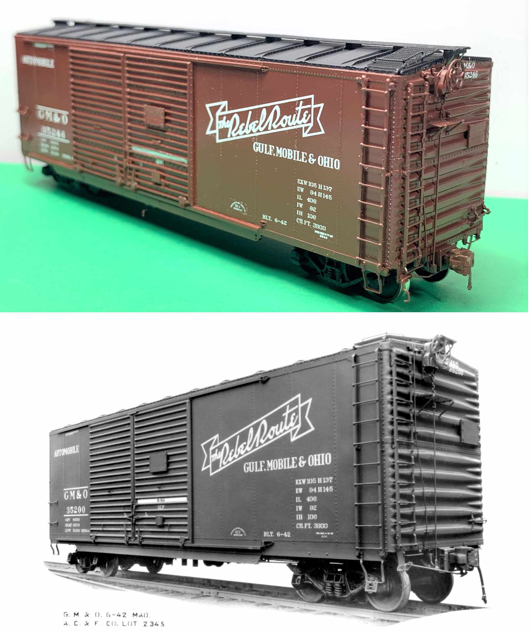
I used Vallejo paint for this car. You can compare my model with the ACF Industries builder’s photo above.
I hope you enjoyed my notes on building this GM&O automobile boxcar. It was a fun project that took much longer than expected.
Thanks to new technology and friends, it is finally finished. I really enjoy working with different and newer materials that we have available today. I thank both Ed Hawkins and Jim King for their help om this project. – – George
Well, George does it again with an outstanding model! Many thanks to George Toman for sharing his modeling techniques on this wonderful automobile boxcar.
Questions and comments can be posted below. Please follow the instructions so your comment can be posted. All comments are reviewed and approved before they appear. To subscribe to this blog, add your email address to the function at the bottom of the right column on the main page. Share the blog link with other model railroaders.
This is top shelf stuff George! Stunning. Thanks for documenting and sharing.
George another freight car build exhibiting excellent craftsmanship. Well done.
I would like to thank all for their kind comments and also thank Frank and Eric at RCW for making these posts possible
George
You hit another home run. I marvel at your precision on 1/87 models. Jim King’s ladder and grab irons look very good.
Fantastic model and clear, concise description of techniques and materials used. Thanks for sharing.