Jerry Hamsmith shares part two of the Central of New Jersey automobile box car build.
This post continues the discussion of the addition of the underframe details. The first post ended with the observation that the AB control valve and the reservoir were placed on the same side of the center sill. Although that was common practice on converted brake system cars with deep fishbelly center sills, it was not as common on cars with a standard center sill as on this CNJ car.
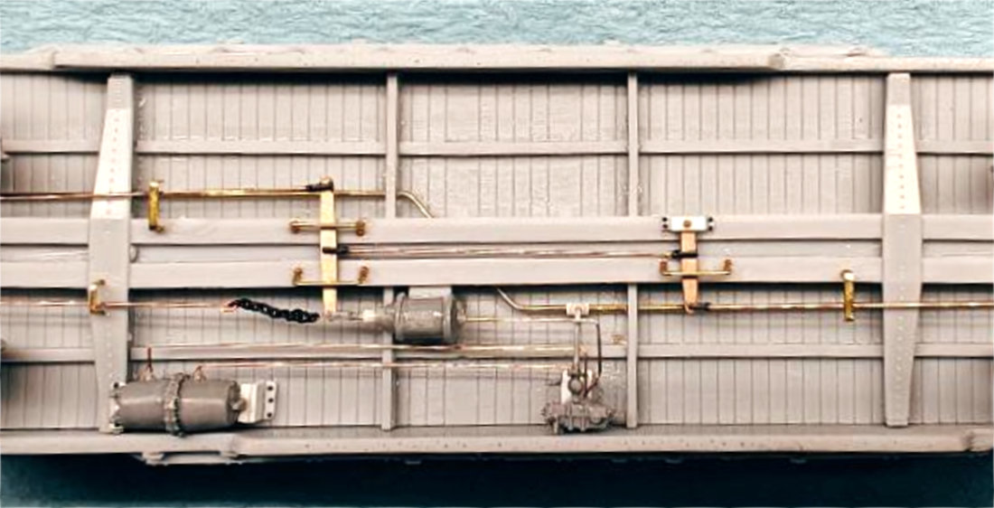
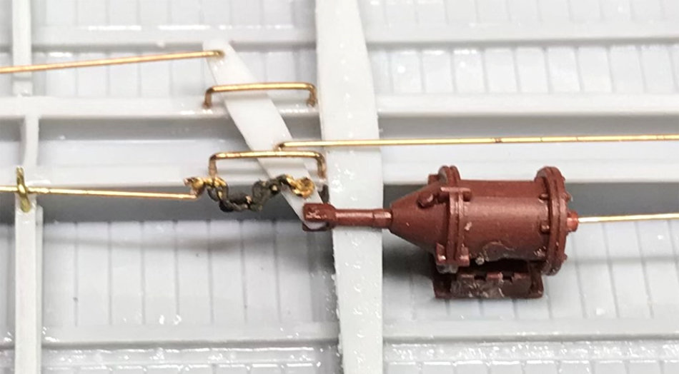
On Jerry Hamsmith’s build, once the reservoir to control valve piping was finished, he added a Cal Scale cylinder and mounted it on scrap styrene so that the piston was slightly above the center sill. The piping connection from the cylinder to the control valve was added using 0.010-inch diameter phosphor-bronze wire (PBW). The dirt collector from the Tichy AB set was glued to the control valve. Next, a scrap of 4×4 styrene was glued to the center sill and the fixed brake lever was mounted to it. The final step was to add the brake rods of 0.010-inch diameter wire and the lever guards using 18-inch straight grabs.
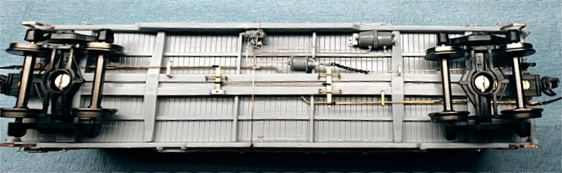
Jerry Zeman used the Tichy sprue parts for his brake system. In the above photo, he has not yet added the cylinder piston or the brake levers. He also used the kit supplied coupler boxes and shortened them for #158 Kadee couplers.
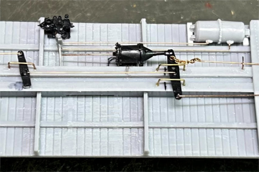
Ed Rethwisch used the kit provided Tichy parts but substituted Yarmouth Model Works levers. He enhanced the details by creating his own styrene mounts with Tichy rivets (tan ones) and harvested rivets from an Athearn gondola (black ones). Each modeler added a dirt collector for the control valve from the Tichy sprue.
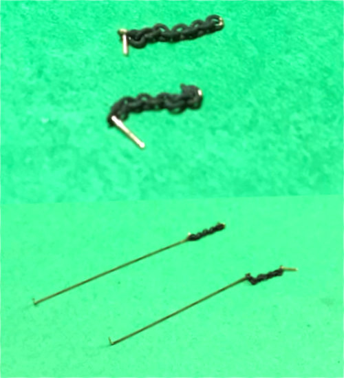
The technique to add the chain to the end of the cylinder piston was covered in this previous box car build, near the end of the post. Other methods could be used. Some of the group members used a half of a turnbuckle as the attachment point.
Before adding the brake rod and chain to the car, a #78 bit was used to drill a hole in the floating lever next to the cylinder piston, just inward of the end of the lever. The lever was inserted into the notch in the cylinder piston and glued in place.
The cylinder was attached to the car floor. About a ten-link piece of brake chain was used (40 links per inch chain from Campbell). The end links were opened up slightly with a #78 bit for a short piece of 0.010-inch diameter wire was inserted into one end link then bent around as a closed hook and glued.
Another length of 0.010-inch diameter wire was fed through the other end link, then finished similar to the first one. This wire was cut to length to run toward the B end of the car to attach near the bolster. The entire assembly was glued into the hole next to the cylinder rod and the insertion wire snipped short. The other end of the rod was glued into the center sill.
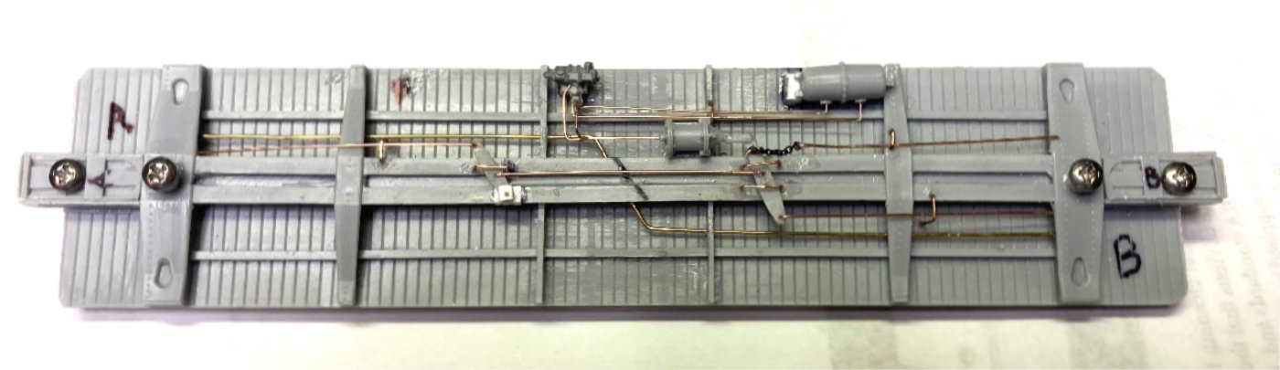
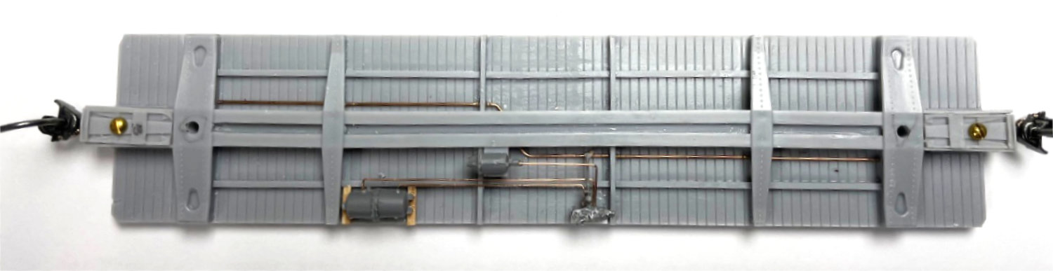
Using the provided Tichy brake components, Allen DeBraal created a fully detailed underframe, as seen above. He created supports for the brake components from styrene. Various guides for the brake rods were created from 0.010-inch diameter brass wire pieces.
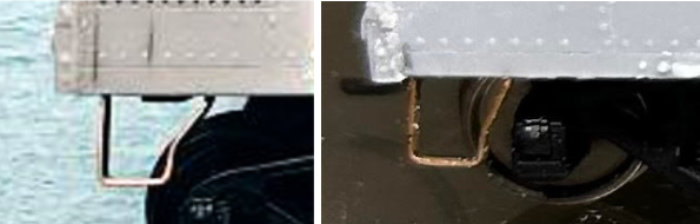
The last step at this time to finish off the underframe detailing is to add the sill steps. The kit provided A-Line style A steps are not correctly shaped and need to be modified. Alternatively, A-Line style C steps could be used (#29002) as they have a much closer to the prototype shape. The sill steps could also be fashioned from brass strips. The left photo above shows the effort of Ed Rethwisch to fashion his own sill steps. The right photo shows Jerry Hamsmith’s use of the “C” style steps.
Following the prototype photos for placement, a #75 bit was used to drill holes into the bottom of the car body at the appropriate locations. The sill steps were inserted and glued into place.
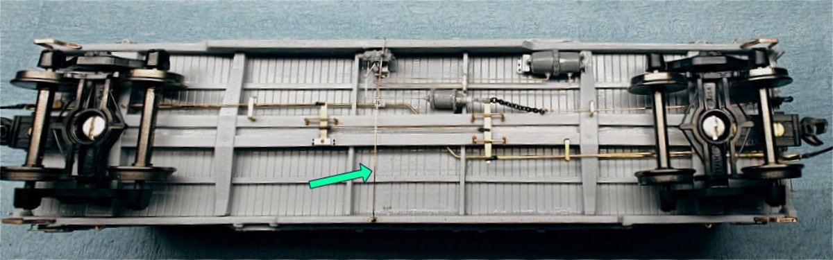
For those wishing to do so, the pressure release rod would be another underframe detail to add. An arrow points to the detail in the photos above and below.
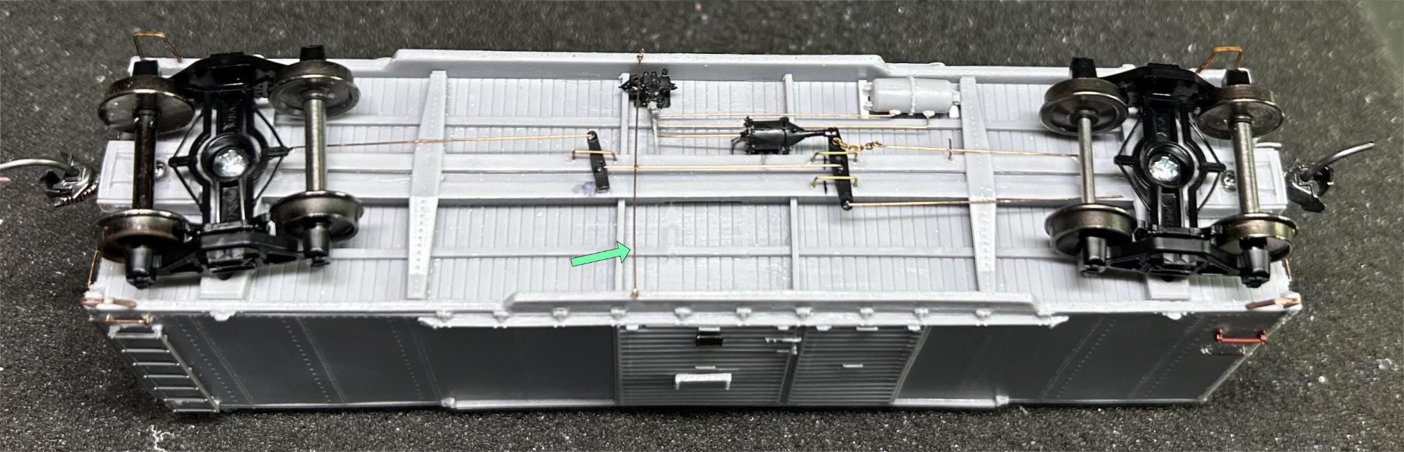
Due to its fragility, the release rod won’t be added until the very end of the build. Not all the group members decided to add this detail.
After joining the underframe to the body, we were ready to tackle the body details. The next segment will describe our efforts at attaching the side and some end details.
Thank you, Jerry and your Modeling Crew for another installment on this group kit build! There’s more to come!
Subscribe to the Resin Car Works blog so you don’t miss a new model announcement. Add your email address to the Subscribe function at the bottom of the page.
Questions and comments can be posted below. Please follow the instructions so your comment can be posted. All comments are reviewed and approved before they appear. Share the blog link with other model railroaders.
Excellent work on both models!
Good job gentlemen, nicely done. Thanks for sharing
Fenton