Jerry Hamsmith has compiled a post covering a group build for a Resin Car Works kit. Here’s Jerry with the details.
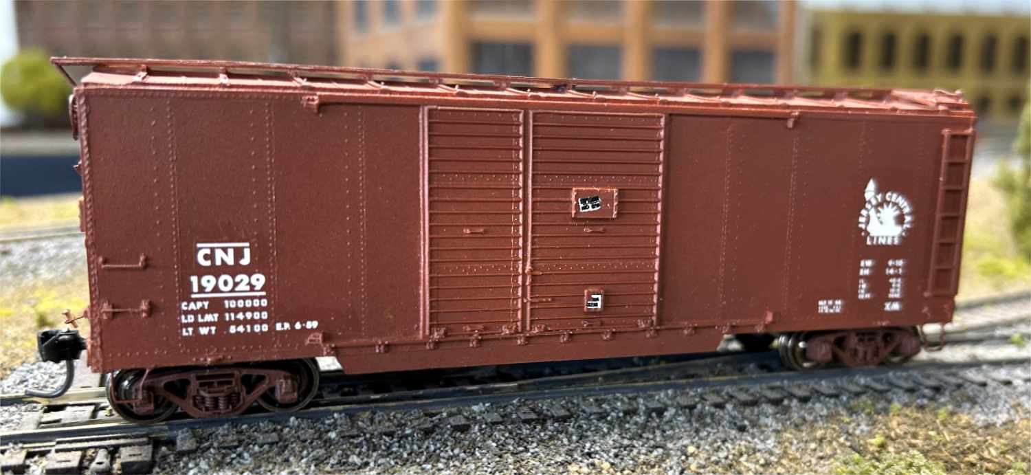
Recently, a group of fellow modelers (Ed Rethwisch, Bob Hanmer, Allen DeBraal, Jerry Zeman, and myself) successfully completed a build of the newly released Resin Car Works Kit 19.01, a Central Railroad of New Jersey 1923 door-and-a-half automobile box car. This series of posts will follow along with the build and describe our techniques. We hope this encourages modelers to build any resin kit and, specifically, aid in building this RCW kit.
Prototype
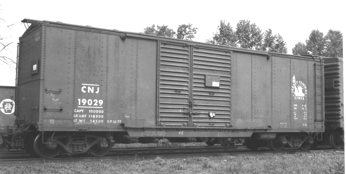
The background prototype information and a description of kit parts are available on the Resin Car Works Kit 19.1 Extras pages. That information should be reviewed as a starting point.
First steps
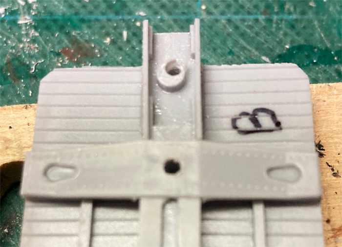
After familiarizing ourselves with the parts provided, most of the group began with the underframe. After removing any flash, the resin castings were washed in warm water and Dawn dish detergent. When the floor casting was dry, holes were marked for the bolsters and drilled with a #50 bit for 2/56 screws.
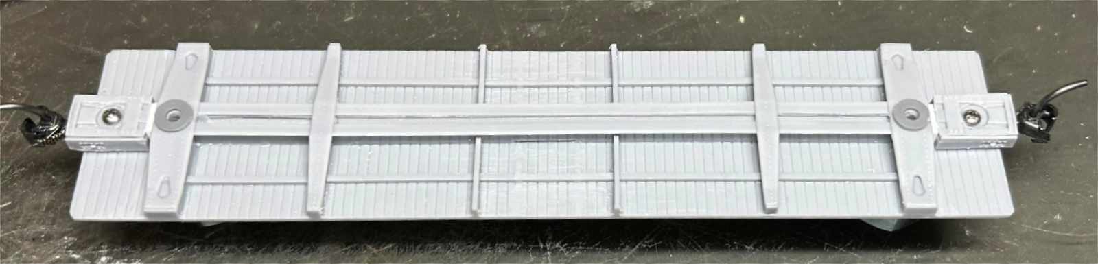
Looking at the floor casting and the coupler boxes supplied, it became obvious that there was going to be a problem. The prototype car was built to the proposed 1923 ARA standards and, as such, has a truck center to striking plate distance of five-feet, zero-inches. The coupler pockets supplied in the kit are designed for a five-feet, six-inch length. So, either they need to be shortened by six scale inches or replaced with another part.
The photo above shows Jerry Hamsmith’s solution – using a different shorter box that also allowed him to use his standard Kadee #5 couplers.
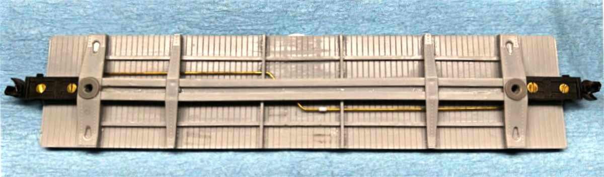
Ed Rethwisch used shortened Accumate scale size boxes and couplers. He also added a train line (0.019-inch diameter wire) to his build.
Next, the kit provided Tahoe Model Works double-truss truck sideframes and appropriate wheelsets were attached to the car and the resulting coupler height was tested. In all circumstances, the couplers were too low and spacer washers were added over the bolster holes. The washers included on the Tichy AB brake sprue provided the correct height adjustment.
Allen DeBraal used the coupler pockets provided in the kit and shortened them by the six scale inches.
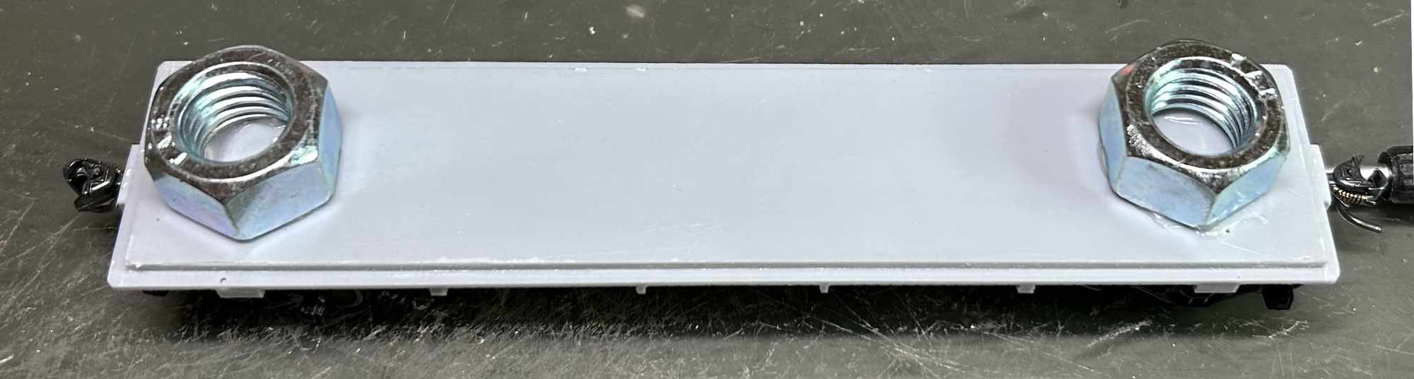
A method to add weight to the car was determined by each member. Some used a flat piece of steel or lead glued to the top of underframe casting, others used “tire weights. The above photo shows the use of a pair of half-inch hex nuts. These are easily found at any hardware store and attached with Formula 560 canopy glue. Once the glue had set, an additional bead of cyanoacrylate (CA) glue was added around the outside edges of the hex nuts to secure them further.
Underframe details
Some members decided to permanently attach the underframe to the car body at this time. Others opted to wait until the brake components were added.
The prototype photos available do not offer a definitive view of the underbody brake system. However, it does appear that the cars had a somewhat different than normal arrangement of the components after the addition of AB air brakes.
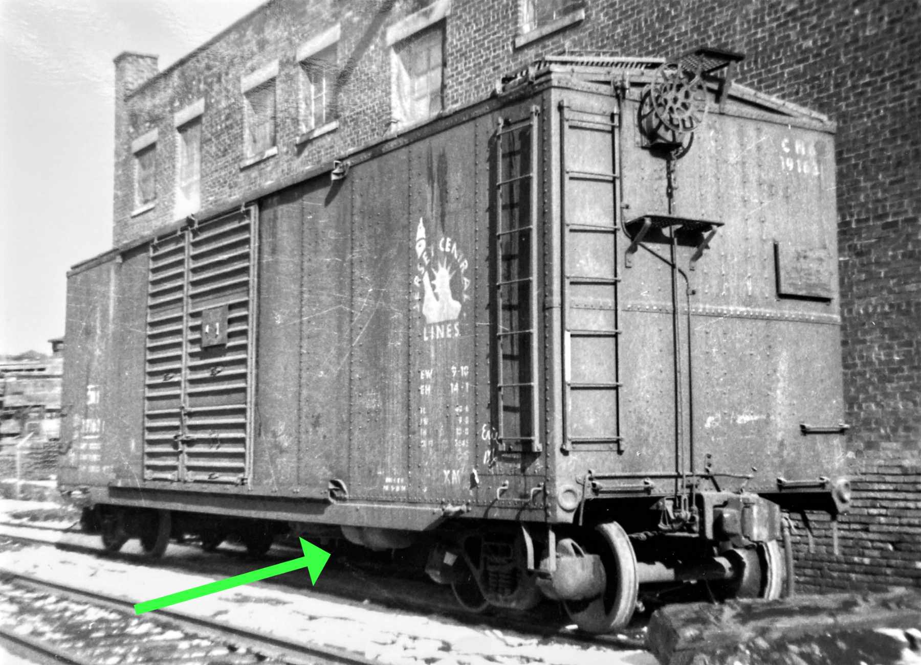
In the photo above, car 19163 clearly has the reservoir mounted on the right side of the car, near the side sill, and about at the end of the door guide. In his instruction photos, Frank Hodina determined the prototype placement of the reservoir and control valve were on the same side of the center sill. We all followed that placement.
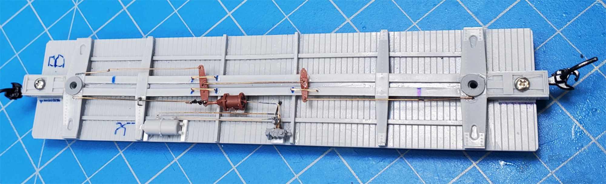
After the locations of the components and levers were marked on the floor, the reservoir and control valve were added.
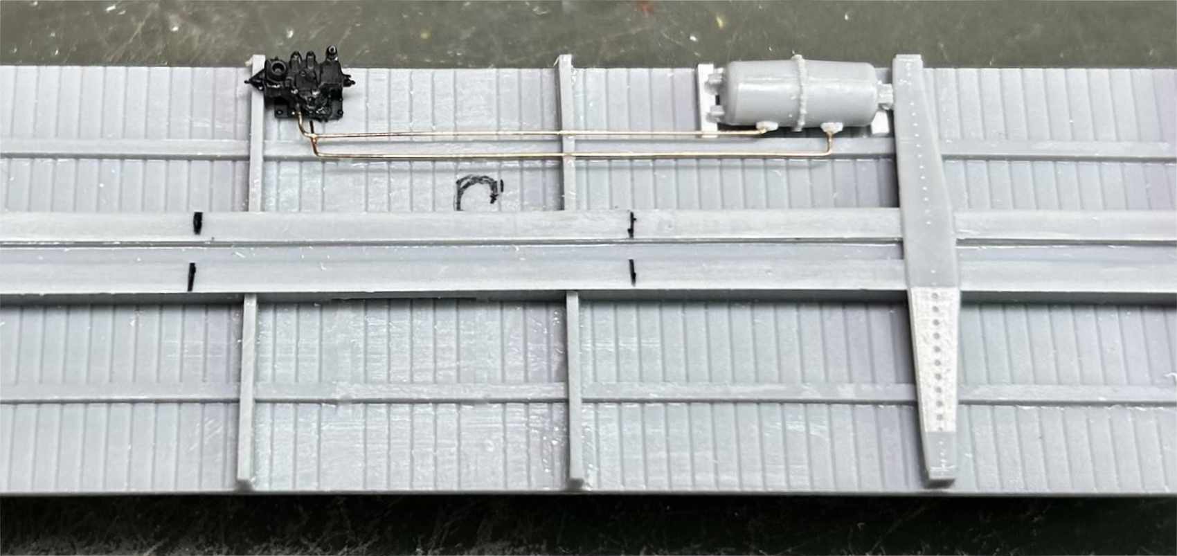
The photo above shows one of the builds, with locations marked and the beginnings of the details added. Due to the space constraints caused by the component placements, the piping between the reservoir and the control valve was added before continuing. For the build above, the reservoir is from the kit parts, but the control valve is part of the Cal Scale AB set (AB-283). The mounts are 4 x 4 styrene for the reservoir and the Cal Scale mount for the control valve. The wire is 0.010-inch diameter phosphor bronze from Tichy (#1101).
The next installment will continue the discussion of adding the underbody brake system and sill steps.
Thank you, Jerry and your Modeling Crew! I am looking forward to the next installments of this freight car kit build.
Subscribe to the Resin Car Works blog so you don’t miss a new model announcement. Add your email address to the Subscribe function at the bottom of the page.
Questions and comments can be posted below. Please follow the instructions so your comment can be posted. All comments are reviewed and approved before they appear. Share the blog link with other model railroaders.
Starting with the A end and moving clockwise, the sequence is A end, right side, B end, left side, so I believe the air reservoir is on the left side of the car, not the right side. Minor point, as the actual mounting position is correct on the model.