
Peter Hall has been busy on a few projects. He sent the following details on his latest freight car build. Click on any image here to review a larger size.
I recently had an opportunity to build one of these fine HO scale models from Speedwitch Media. The mold work for the castings is beautiful and well-detailed, and the kit goes together very nicely.
On starting the kit, I found the instructions contained many excellent photographs showing the assembly steps. I found additional helpful photos in Ted Culotta’s “Focus on Freight Cars – Volume 1,” and Tony Thompson’s “Southern Pacific Freight Cars – Volume 3.” One of these cars, the SP 63728, is shown at Harrisburg, PA, on July 20, 1947, which puts it in perfect chronology with my layout.
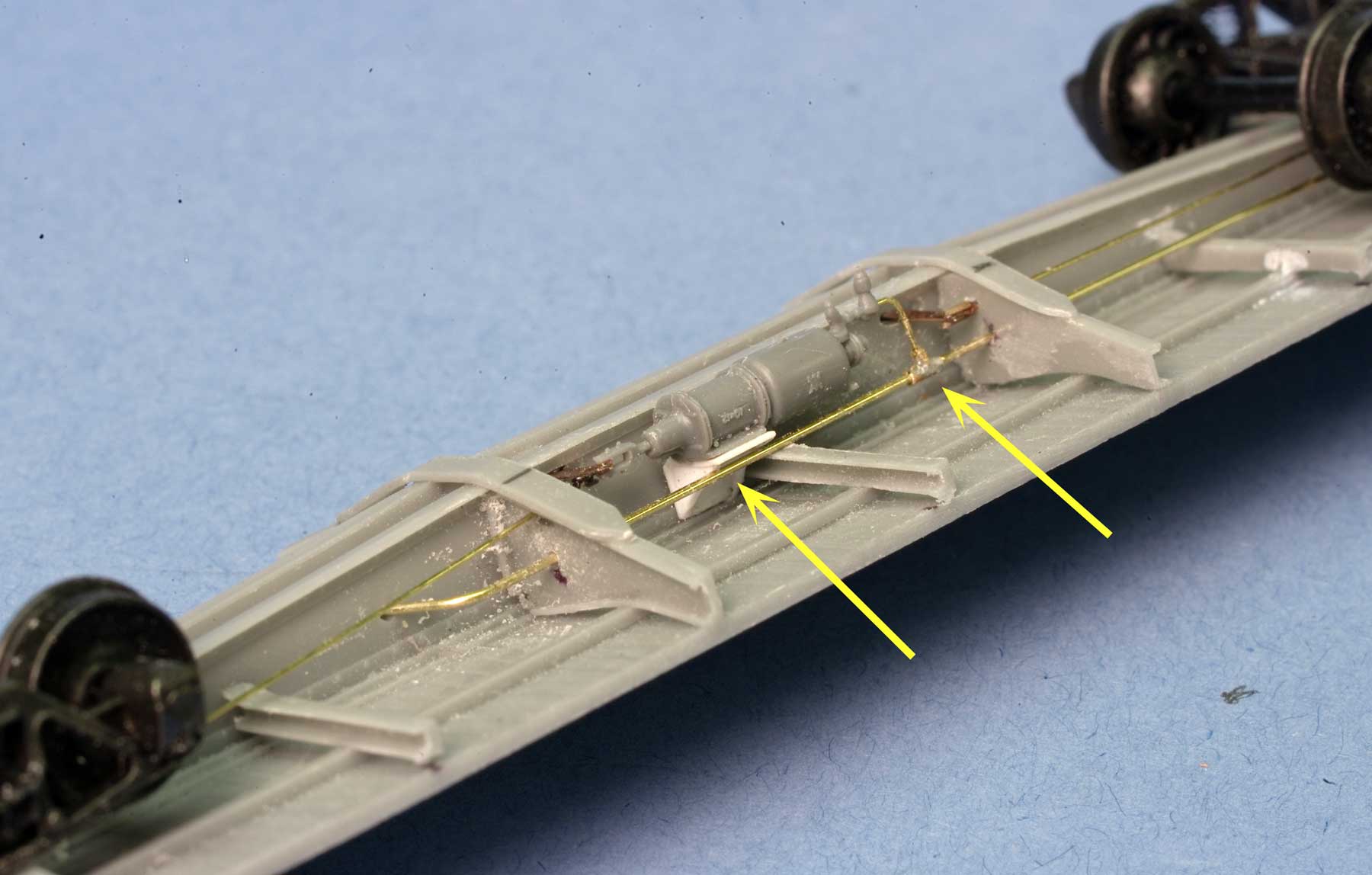
The first step in the instructions is to add the weights to the floor. However, I delayed the step until after the car was fully painted, because I found working with the floor was much easier when I could lay it flat on the workbench to drill the holes and add the parts.
I added full brake rigging and needed a replacement brake support bracket, so I made one from a styrene 0.188-inch H-beam and two squares of 0.010 x 0.188-inch styrene. I also built a T-joint from brass tubing for the air line to the brake reservoir.
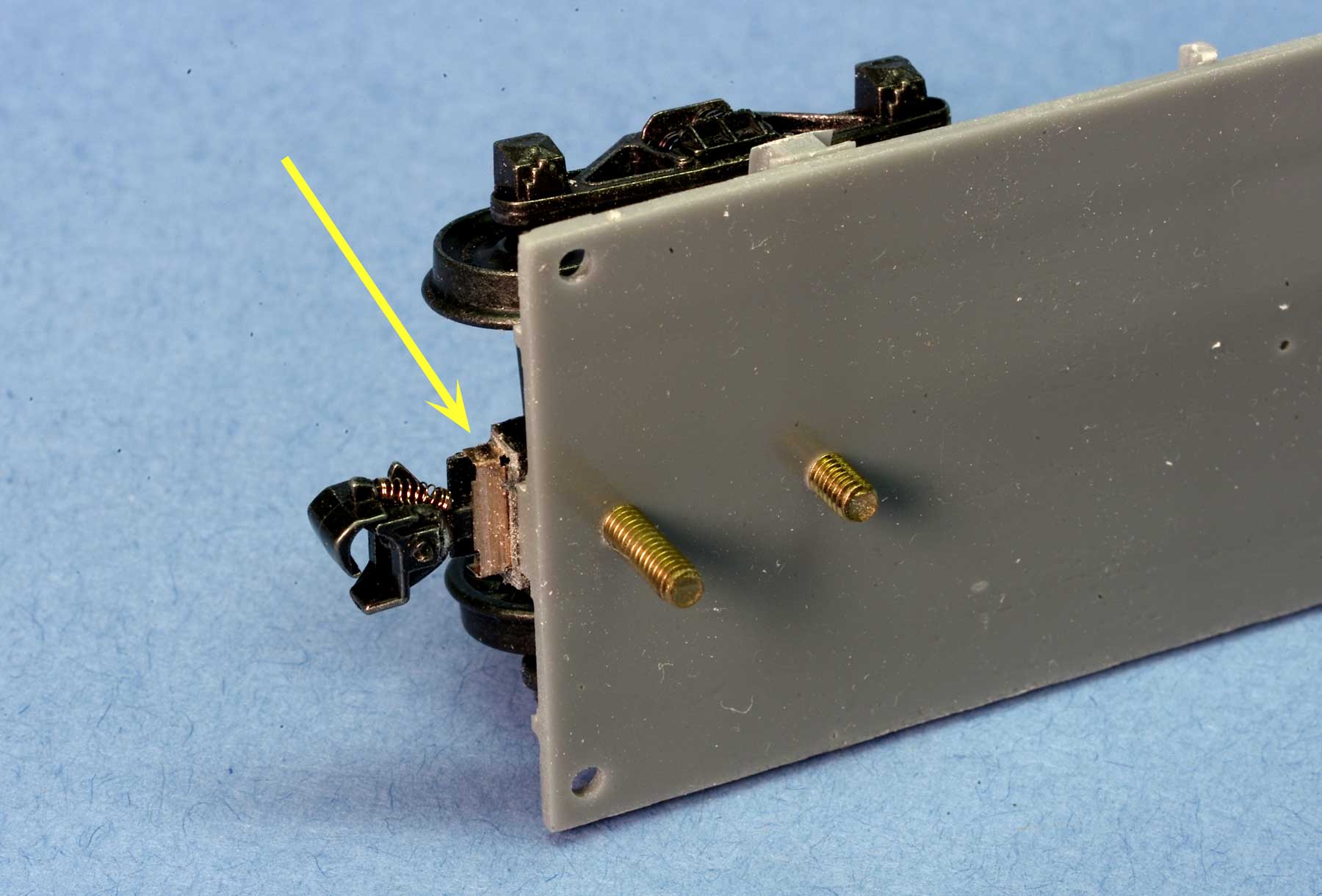
I wanted to mount the coupler draft box with screws, and found I could modify a standard Kadee coupler box by removing 0.080-inches from the top and the sides of the box so it would fit inside the molded coupler box on the body.
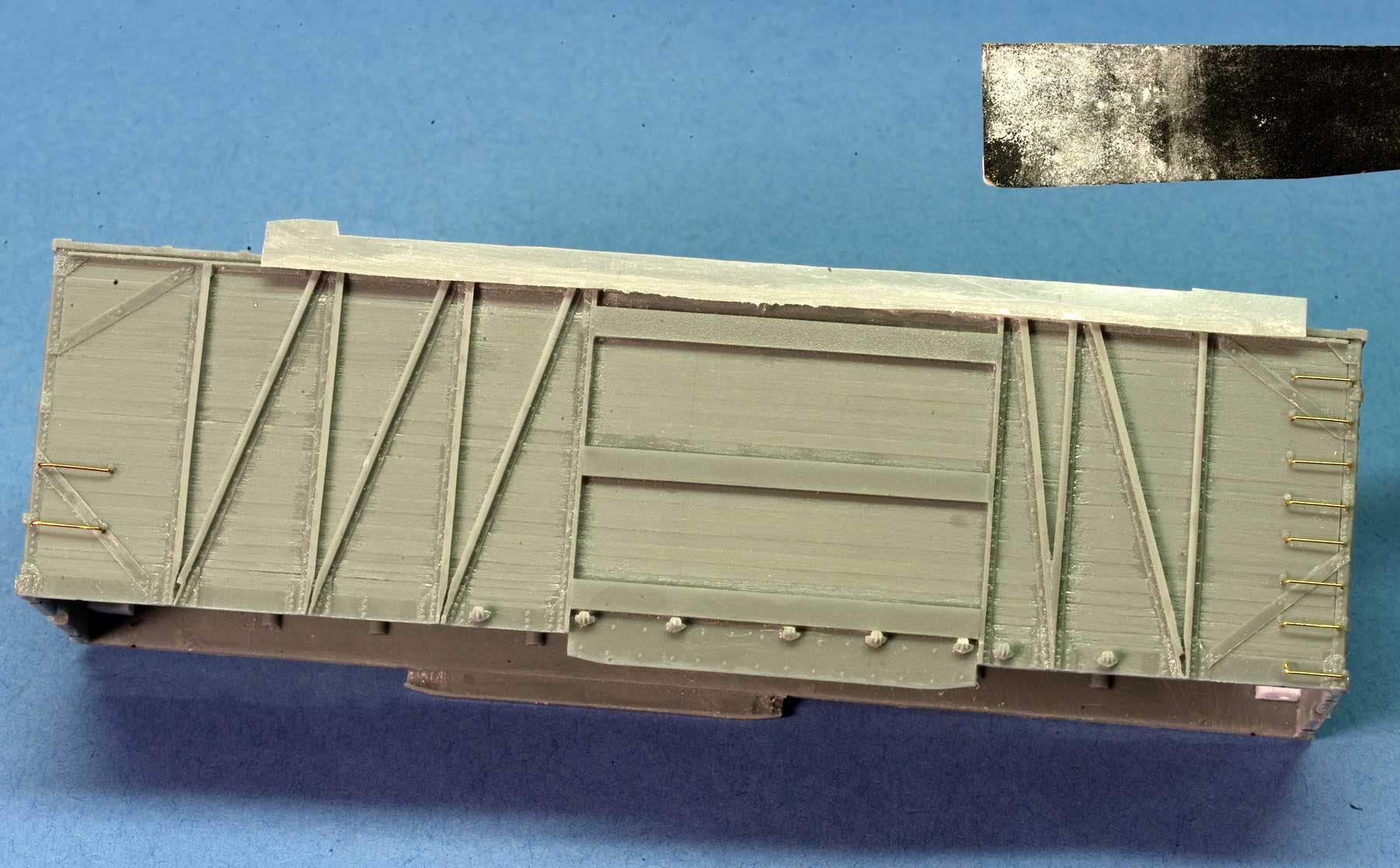
Attaching the top of the door track was very tricky. It’s thin and delicate but becomes very solid when attached. The trick I used was to remove some of the flash from the “bottom” of the part with a sharp knife, then use the remaining flash as a handle to hold the thin strip alongside the track on the body. The strip to be added has rivets cast into the top of a thin extension which was glued onto the top of the door track. Once the door track extension was solidly attached to the car, I used 320-grit sandpaper to remove the flash from the part.
The next step was to detail the ends, which involved bending a long piece of etched brass lengthwise. I wasn’t satisfied with my results, so I used another method. The Des Plaines Hobbies 8-rung ladders (part # DPH 2003) are exactly the right size and spacing to match the grabs on the side of the body, and they have nice Nut-Bolt-Washer castings on the stiles at each rung. However, the rungs on the plastic ladder didn’t protrude from the stiles like they did on the prototype. So, I glued the ladders to the brackets on the body so that the NBW castings were even with the NBWs cast into the side. When the glue was dry, I was able to snip the rungs from the ladder, drill new holes just below each NBW, and insert new wire grabs into the ladder.
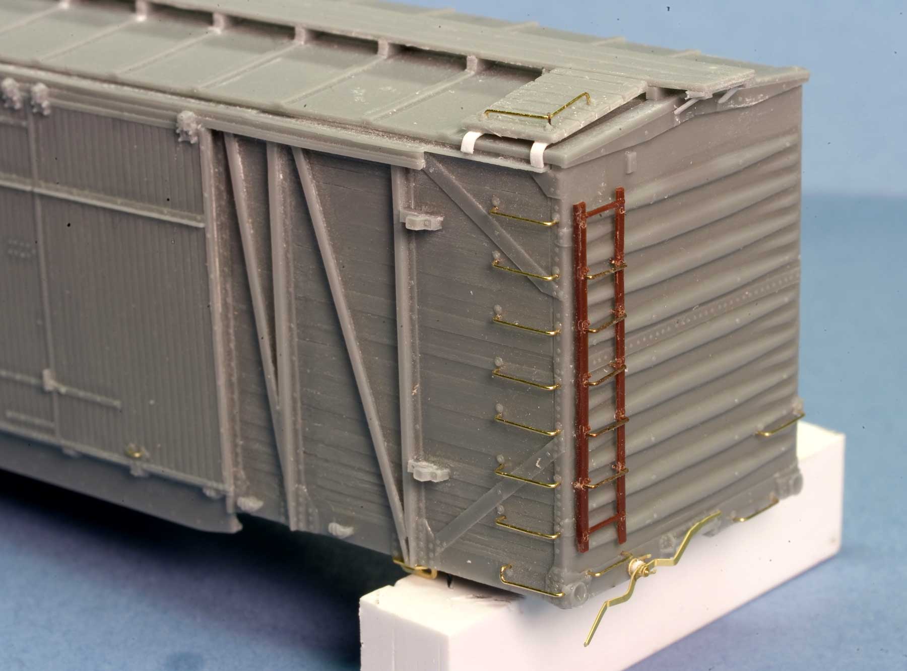
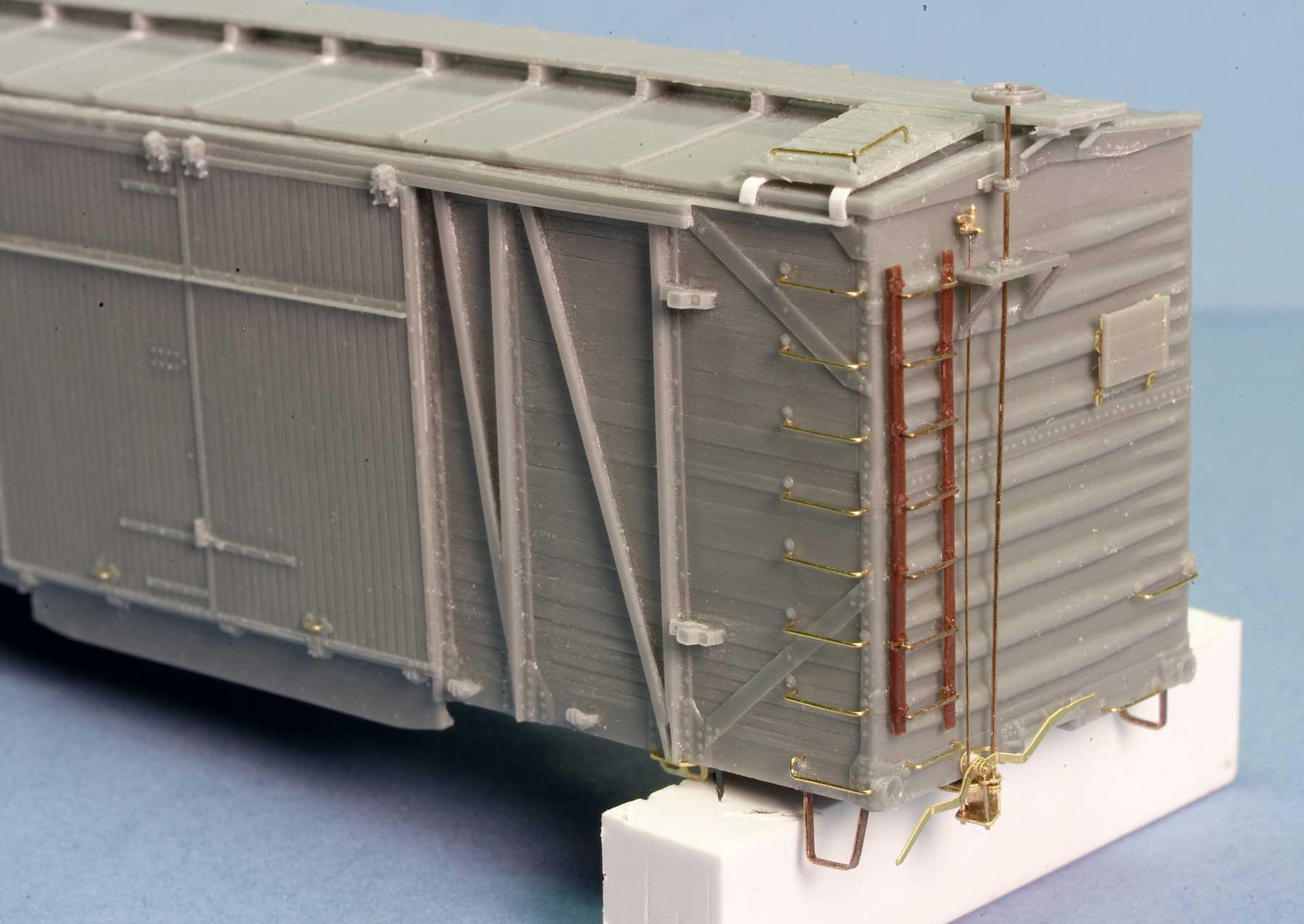
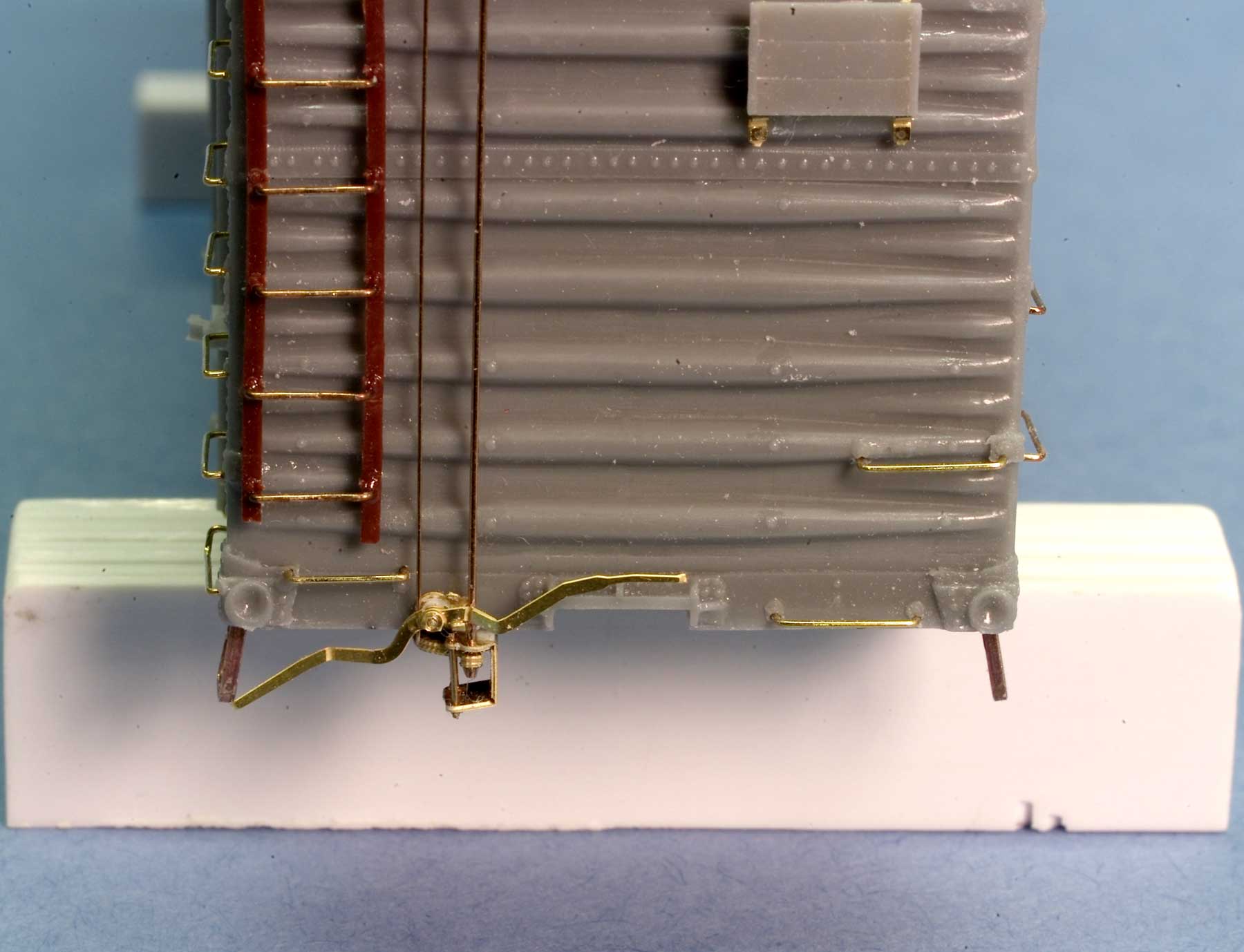
I finished detailing the ends, including building the Carmer levers. This was a really nice detail built from very tiny etched parts that are provided in the kit. It was important to locate the Carmer pivot point properly. The retainer line had to run between the left grab iron and the left side of the Carmer pivot, and the hand brake shaft had to fit in the “pocket” of the Carmer lever on the right side. Also, the brake step must be placed so that the retainer line runs inside the left brake step bracket, and also so that the brake shaft runs vertically up from the gear bracket. That’s a lot of adjustment for some small parts.
The “powered” handbrake has a small gear at the bottom of the shaft, and a larger gear just inside on its own shaft. It’s amazing how accurately these tiny parts are etched – the gears actually have teeth. The larger gear shaft would wind up the brake chain; I didn’t model the chain, as it would need to be glued to the floor, which is removable. I did make sure the gear housing did not protrude into the body cavity, so that the floor could be inserted later.

Here you can also see the 0.188 x 0.188-inch blocks I glued to the inside of each corner to enable the floor to be secured by four screws. The holes were drilled and tapped for NWSL 1.7mm screws. They have very small heads, which keeps them away from the truck wheel flanges.
I also broke two door stops during the removal of flash, so I built two new ones from small styrene shapes. And yes, I did add the Archer rivet on the end of each brace for the roof laterals.

One additional, very valuable thing I learned from building this kit was how to use tiny Carbide drill bits. The 0.3mm and 0.4mm bits are very sharp and tough, but tend to break easily in resin. I commented on this recently, and a friend told me that the trick was to put soap on the tip of the drill bit before starting to drill. I dipped the bits into liquid detergent, and used a Dremel flex-shaft at slow speed. Drilling a little at a time, cleaning the bit and re-soaping each time worked very successfully.
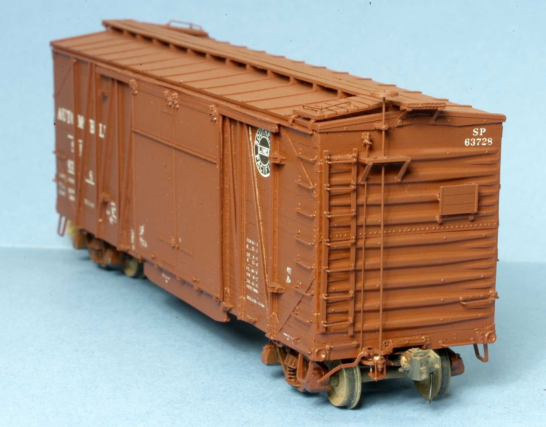
This kit builds into a unique model I believe is not available anywhere else, and I’m glad to have it as a new arrival in the fleet.
Thanks to Peter Hall for sharing his build notes on the Speedwitch Media SP A-50-4 Automobile box car kit. We think Peter’s work will inspire people to move a resin freight car kit from the workbench to service on their layout.
Questions and comments can be posted below. Please follow the instructions so your comment can be posted. All comments are reviewed and approved before they appear. To subscribe to this blog, enter your info for a comment and check the last box to notify of new posts by email. Share the blog link with other model railroaders.
Precision Scale has pipe fitting castings including a T-connector that I’ve used to connect the control valve to the train line. Unfortunately, they don’t give the size of wire for part GH-48196, but GH-48171 has a 0.018 in. core, so that would work for train lines. I used a Precision Scale T-connector casting that came in a kit once, but I don’t know which part number it was. Has anyone else used Precision Scale T-connectors and know which part number works best for train line connections?
The Precision Catalog has the GH-481196 T-connector listed with a .032 core. So these look to be a bit to big.
Peter,
I built mine as a T&NO car and I agree that this kit includes some truly outstanding casting and etchings. I built mine strictly following kit instructions but your upgrades add much to the finished model. I like what you did with the end ladders. That inspires me to revisit that detail somewhere in the future.
Thanks for sharing.
Great job, Pete! The step by step photos are well done, too.
I’ve never seen the curved edge of the cross bearers against the frame members. Did SP really do that, or they mounted upside down? Normally, the flat edge is against the frame. Beautiful straight grab irons, ladder, and end detail.
Apparently so, because the castings are built that way, and the instructions show the crossbearers mounted that way. I sure hope so!
Beautifully made Peter I particularly like the brake pipes.
Paul Doggett UK
I have had fits trying to sort out how to assemble that gear arrangement for the brake wheel but Peter clearly nailed it. I am going to re-engage this assembly and hopefully finish my kit as this is only step left to complete. Very well done Peter! I hope this will inspire others to try resin.
Peter, What a terrific job you did on building this car. I really like your attention to the small details. Your T -joint for the air line is a nice touch. What size brass tubing did you use and where did you purchase it? Thanks for sharing details on its construction . Looks great all painted up.
Thanks! I used two lengths of Albion Alloys Ltd brass tube soldered together. I filed a recess into the end of one piece and mounted it perpendicularly to the other. Des Plaines Hobbies in Des Plaines, IL, has a good supply of Albion Alloys products – many shapes and sizes that are very small, ideal for things like this air line.