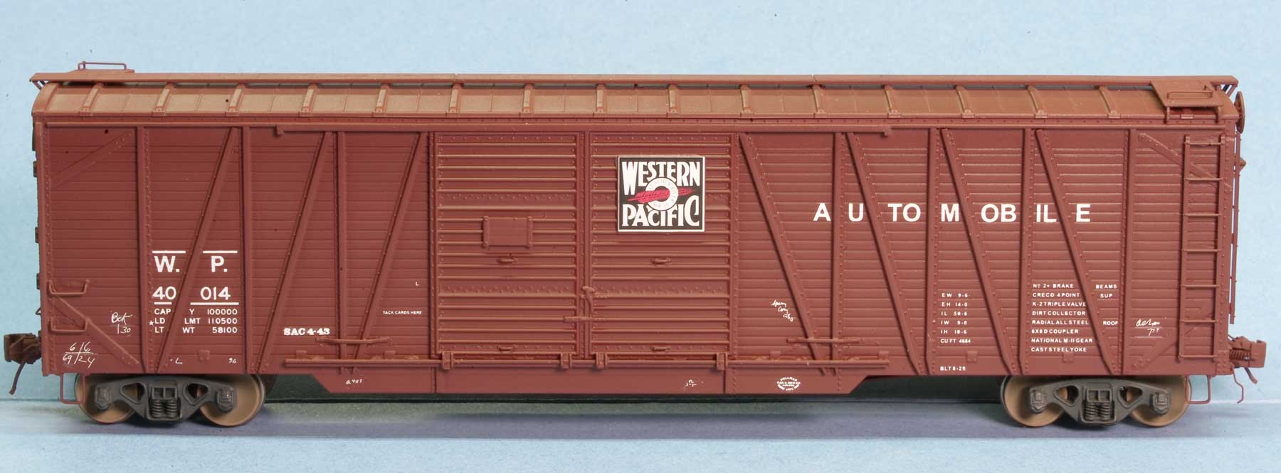
Pete Hall has been busy working through a few projects. Here’s his update on a pair of HO scale Western Pacific automobile box cars.
I had two 50-foot MDC/Roundhouse single-sheathed automobile box cars with end doors that were lettered for Southern Pacific, but the bracing was wrong. They languished in a drawer until Frank Hodina sent me reprints of some old articles about this car. These cars can be made into very good models of Western Pacific (and others) 40000-series prototypes with some work. I owe a debt of gratitude to Frank and to those who have published articles on this process before me. Click on any image here to review a larger size.
SIDES
First, I removed the roof running boards and sanded them from a thickness of about 0.045-inches down to about 0.025-inches. I left them off the car while I carved off all of the cast-on ladders and grabs, the handbrake rod, the brake step and the retainer line. This was a tedious process requiring a lot of patience, sharp knives, and sandpaper, but the end result was clean sides and ends. The end tack boards were good ones, so I left them in place and used drill bits beneath the boards to create gaps. At this time, I also removed the existing SP lettering.
I worked on the sides first without the ladders, because the added details would be fragile. I added an Albion Products 1mm “L” at the bottom of each door. Cyanoacrylate adhesive (CA) held it against the existing door rollers. To simulate the guides at the bottoms of the doors, I used 0.060-inch channel mounted vertically. The top and bottom of each rail of each channel were cut and sanded at an angle to give the right profile. Two bits of 0.020 x 0.030-inch styrene were used as stops at the ends of the door top rails. The two herald plates were 0.010-inch styrene sheet, sized 0.460 x 0.520-inch to accept Microscale WP herald decals.
Perhaps the hardest part of the door modification was removing the four very small cast-on hand grabs and replacing them with 0.010-inch wire. Drilling the tiny parallel holes required a lot of magnification. Then I drilled #80 holes for all the other hand grabs in the sides and ends, using A-Line #29100 for the drop grabs and bending 0.012-inch wire for the straight ones.
The ladders were a challenge. The best ladders that I found for these cars were Detail Associates #6242 with 7 rungs at 18.5-inch spacing. They are very delicate and require great care to remove from the sprue without damaging the bottom rung, but they look great in place. I added bits of 0.020 x 0.030-inch styrene at the middle of the side ladders, and at the middle and bottom of the end ladders. I drilled locating holes and inserted the top and bottom pins of the ladders. The styrene bits are glued to the sides and provide additional strength.
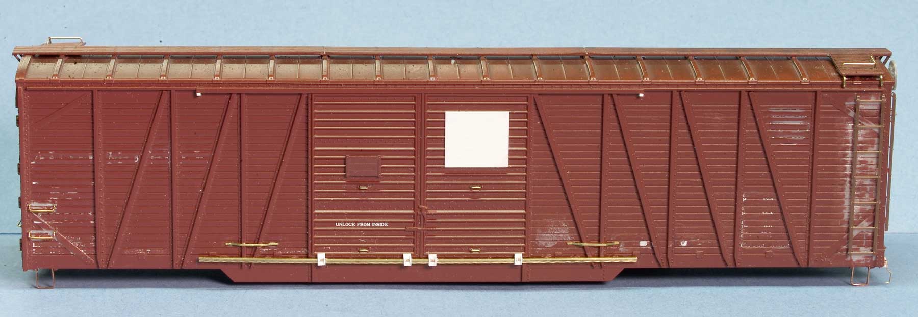
The two door guides on each side were 0.010 x 0.018-inch flat bar strips glued to the sides. The 3-board tack boards were from a Red Caboose box car sprue.
At this point, I reinstalled the roof running boards, and added strips of 0.010 x 0.018-inch brass flat strips as braces for the laterals. The lateral grabs were 0.012-inch brass wire with Yarmouth Model Works eye bolts in the corners. The running board end braces were two different pieces. Above the end doors these are shorter, and Red Caboose braces work well; on the hand brake end I used Proto2000 braces.
The final step on the sides was to install A-Line stirrup steps. I cut away the existing plastic steps leaving the top horizontal piece at each side, and drilled holes to insert the A-Line stirrups as closely as possible to the existing pieces.
ENDS
The ends required additional work. The ladders are the Details Associates #6242 with the bottom rung removed. This step also removed the locating pins at the bottom of the ladder, so the styrene bits were used as brackets.
The retainers were from Red Caboose/IMWX sprues because they had a larger angle between the two vertical sections. The brake rods were from Proto2000 sprues; the brake step, brackets, and Ajax handbrake wheels were from Tichy Train Group AB sprues. The Ajax housing cast onto the end was the right size and shape, but I carved an opening in the bottom to accept the brake chain/rod. In the image below, the brake rods and cut levers are not yet in place because they connect to the chassis which had been removed for painting.
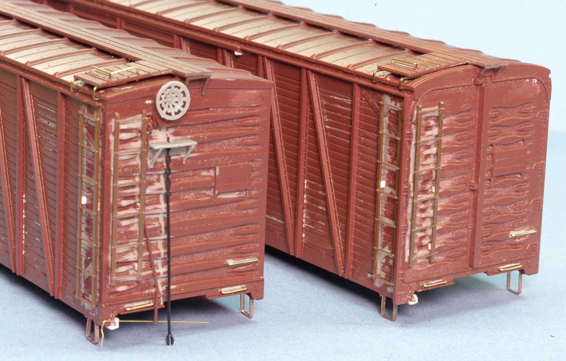
To hold the cut levers, I filed a flat spot on the car and glued bits of 0.060-inch “L” to the bottom edge of the poling pocket flange. A #80 hole was drilled for the 0.010-inch wire cut lever. After doing several projects like this one, I have found that I can make a stockpile of cut levers, bent into common patterns, ready for application when cars become available. Since I’m upgrading my car fleet, I’m using a lot of cut levers.
When the chassis was reinstalled into the shell, I connected the brake rod to the bell crank and glued the cut levers to the bottoms of the coupler pockets.
UNDERBODY
The chassis was detailed with Yarmouth brake levers that fit nicely through the slots already cast into the fishbelly center sills. I joined them with 0.012-inch brass wire brake rods, using Grandt Line plastic turnbuckles for clevises. Holes were drilled in the crossbearers to accept the brake rods. The larger Yarmouth brake lever had a small wire attached to one end, which was shaped into a hook to hold the 40-links-per-inch chain. Another brass wire led off to connect the chain with the bell crank. I moved the brake cylinder 0.080-inch farther away from the crossbearer to give a proper angle for the larger lever and room for the chain.

I removed the existing triple valve and substituted one from a Proto2000 sprue. This valve had cast plastic lines leading away to the reservoir, so I kept the lines, drilled holes through the center sill and inserted the lines. The existing reservoir was actually a better casting than the one on the Proto sprue, so I did not replace it. I also elected to not run air lines away from the reservoir, as it’s nearly impossible to drill holes behind the reservoir, and it’s very difficult to see due to the low side sills. The last step was to drill into the brake cylinder and run a 0.012-inch brass wire to the triple valve.
I added High-Tech Details rubber air hoses to the ends of the car chassis, securing them to the coupler pockets with CA. At this point, since the underbody on the WP car was black, the chassis and trucks were painted with a brown-black mixture of acrylic paints, as well as using a wash of Model Master “Leather” as brownish weathering on the couplers and wheelsets.
FINISHING
The chassis were re-inserted into the shells, the brake rods and cut levers added, and the cars airbrushed with Scalecoat I #S87 Box Car Red # 2. This color is an excellent match for Tru-Color #204 WP BCR. I prefer the surface that Scalecoat provides for decaling. Decals were added from the Microscale MC 4266 set. The cars were oversprayed first with Glosscote to seal the decals and then with Dullcote to give a flat finish. Weathering will be applied when everything is completely dry.

This project has convinced me that many of my older cars with cast-on details can be upgraded if I can’t replace them with better models of the same type. It is a joy to see older cars come alive with the many wonderful detail parts we have today.
We thank Pete Hall for sharing details and photos of his work. There’s a great deal that can be done to upgrade older plastic freight car kits with careful attention to details.
As an addendum, we posted Fred Jansz’s upgrades on the same kit in January. Fred and Pete used different techniques and details but both ended up with remarkable models.
Questions and comments can be posted below. Please follow the instructions so your comment can be posted. All comments are reviewed and approved before they appear. To subscribe to this blog, enter your info for a comment and check the last box to notify of new posts by email. Share the blog link with other model railroaders.
Pete’s mini article is a breath of fresh air as this one of my very favorite single sheathed 50-foot boxcars. I have several of Richard Hendrickson’s favorite black and white photos of these cars that he reviewed when they were first released. I remember the finished cars in the cabinets downstairs in the train room. pete’s mini article makes this a weekend project for those of us that still think styrene is a modelable medium. BRAVO PETE!
Once again, Pete has nailed it.
Larry Buell
Two miles east of Pete.
Pete, your upgrade produced two fine models. Thanks for sharing.
This takes me down memory lane. Years ago, before the MDC 50′ SS Autocar model was released, I asked Richard Hendrickson for a suggestion as to what would be a good 50′ SS box car for me to undertake for my first solo resin project. Richard, the sharing and helpful friend that he was, sent me several B&W photos from his darkroom and some equipment diagrams. He mentioned that the Pullman company built several autocars for the WP, and most of the details were duplicated for an MP order (and their sub. T&P).
I had just finished this project when MDC released the above subject HO model. Years later I inserted my foot into my mouth when I mentioned to Brian Leppert I thought the board grooves were excessive whereupon Brian told me he tooled the model for MDC during the years he worked there. In his defense, he said his boss felt that SS cars needed to be prominent in the execution of the board gaps. Brian took the jab like a gentleman.
My WP 50′ SS car side used faintly scribed lines for the board patterns. I remember back when I was scaling photos for working drawings that to get the board spacing correct, one needed to count the boards between the upper and lower steel sills. I often had to do skips from panel-to-panel to get an unbroken count as many areas did not even show any evidence of gaps at all.
I discovered a casting of a side from this project in my reject box recently. I rejected parts which had surface bubbles, and this part had a few problem areas in the doors and elsewhere.
If anyone is interested in posting a picture of this resin side, I could send it to that volunteer for reposting to this group. Or, simply ask me for a scan at
Pete, Thanks for sharing the modifications and techniques used on this upgrade. It turned out very nice. Great Job.
George Toman