Jerry Hamsmith and his group share an alternative AB brake system installation for the Resin Car Works NYC gondola kit.
Two of the group members decided to do the extra work to follow the AB drawings that were part of the NYCHS shared material. See the Kit Extras instruction files on the RCW website for all of these drawings.
Complete complex AB system
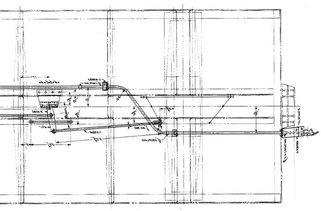
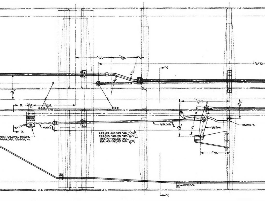
This post focuses on different techniques to create the more complex system only. Portions of the drawings supplied by the NYCHS were enlarged for a better detailed view. Each drawing is oriented looking down from the top of the floor. Following the arrangement requires you to constantly convert things. Since I don’t trust my mind to do that consistently, the drawing was inverted to give a bottom up view consistent with a modeler’s viewpoint.
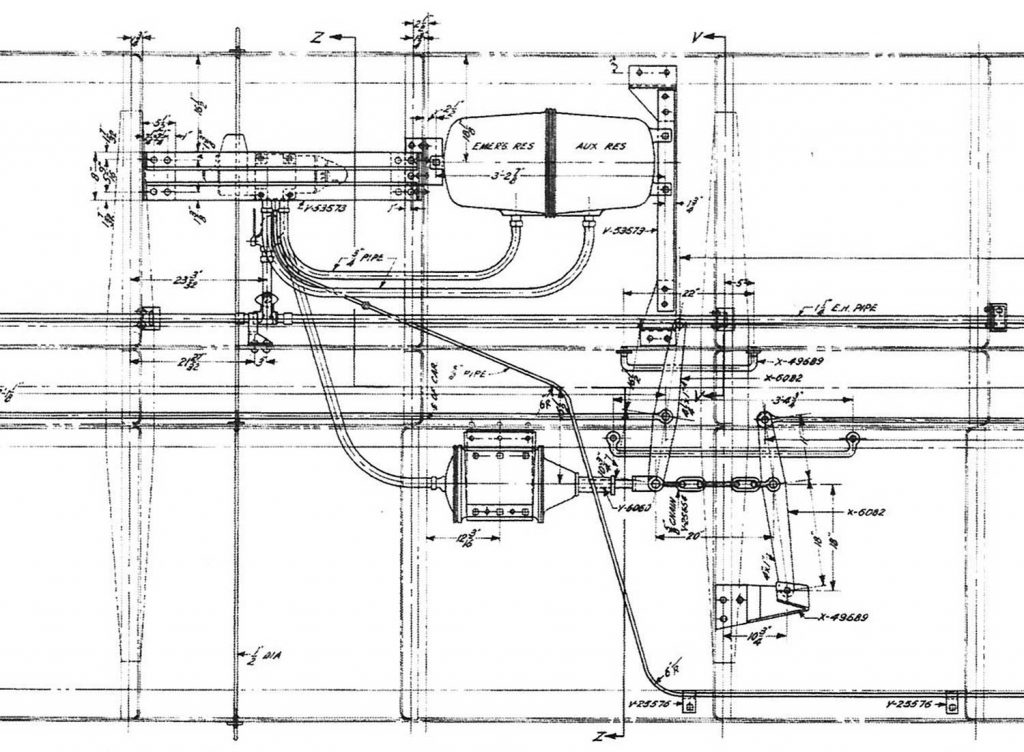
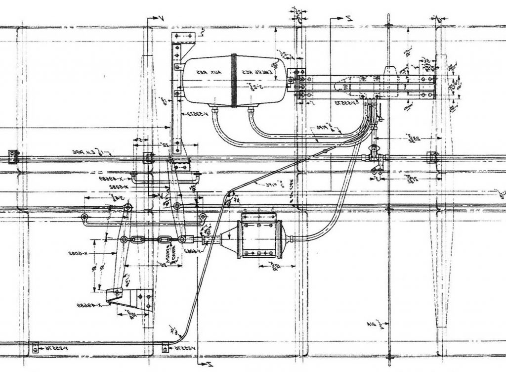
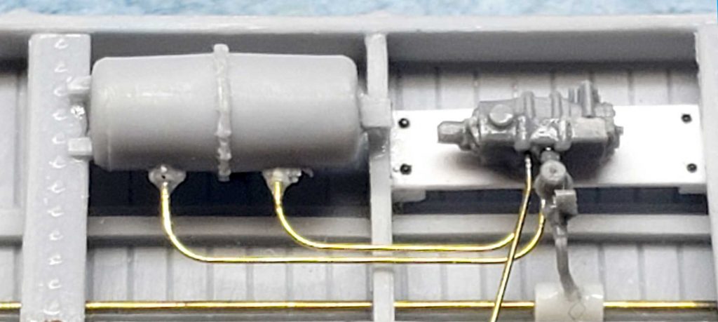
The inverted view shows the control valve supported on a platform. This was created using a 0.080 x 0.015-inch piece of styrene cut to fit between the crossbearers. It rests on a pair of 0.040 x 0.040-inch supports.
The cast on edge supports hold the air reservoir. Note the placement is slightly inboard of the outer edge of the car. These components were the cast resin ones from the kit. Brass wire represents the piping connections. The dirt collector included in the Tichy brake set was added beside the control valve.
A Cal-Scale brake cylinder was installed next. It was positioned across the center sill from the air reservoir. The placement seen in the above image is too close to the crossbearer. The end of the piston should be at the right edge of the crossbearer in the image above. 0.010-inch diameter brass wire connects the cylinder to the control valve.
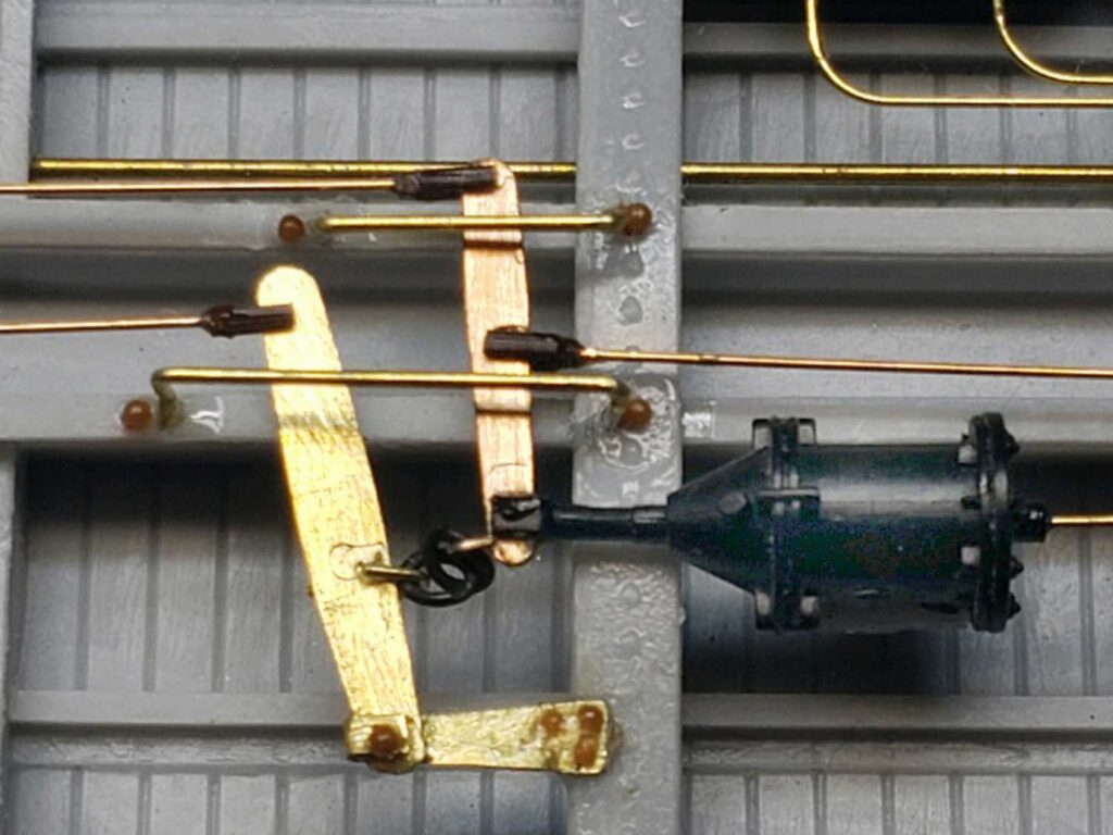
After all the brake piping was completed, the brake rods were started. The most complex arrangement is at the end of the cylinder. Per the drawing, there is a lever at the tip of the cylinder, and a short length of chain connects to another lever. This second lever is anchored off of the crossbearer and is the connection to another lever that is connected to the hand brake. We will cover that lever installation last.
One end of this second lever is sandwiched within the pivot point bracket. Brass was used to construct the bracket due to the bend necessary to create the sandwich. All rivets for the levers and hangers are Tichy, with just the heads used. The clevises are Grandt Line turnbuckles that have been cut in half. Brake rods are 0.010-inch diameter phosphor bronze wire from Tichy. The brake levers in this image are from Yarmouth Model Works. The long lever hangers are 0.010-inch diameter brass wire made following the drawings.
Moving toward the A end of the car, the brake rod parallels the centersill to avoid the drop doors. This would follow the original rod arrangement when the car had K brakes. The rod ends at a secondary lever to operate the brakes on the A end truck.
Following the drawing, a bracket was created to anchor the lever and glued to the center sill. The anchor was created from styrene parts. A 0.040-inch piece was glued to the center sill as a spacer to gain height. A bottom pad of 0.010 x 0.040-inch styrene was shaped per the drawing with 0.020-inch spacers along the edges, and a top piece of 0.010 x 0.030-inch covers the lever pivot point.
The Yarmouth lever was glued into this sandwich then clevises and rodding were added. The lever hangers were fashioned from 0.010” brass wire. The larger rivet heads are Tichy, while the smaller black rivets are harvested from an Athearn gon.
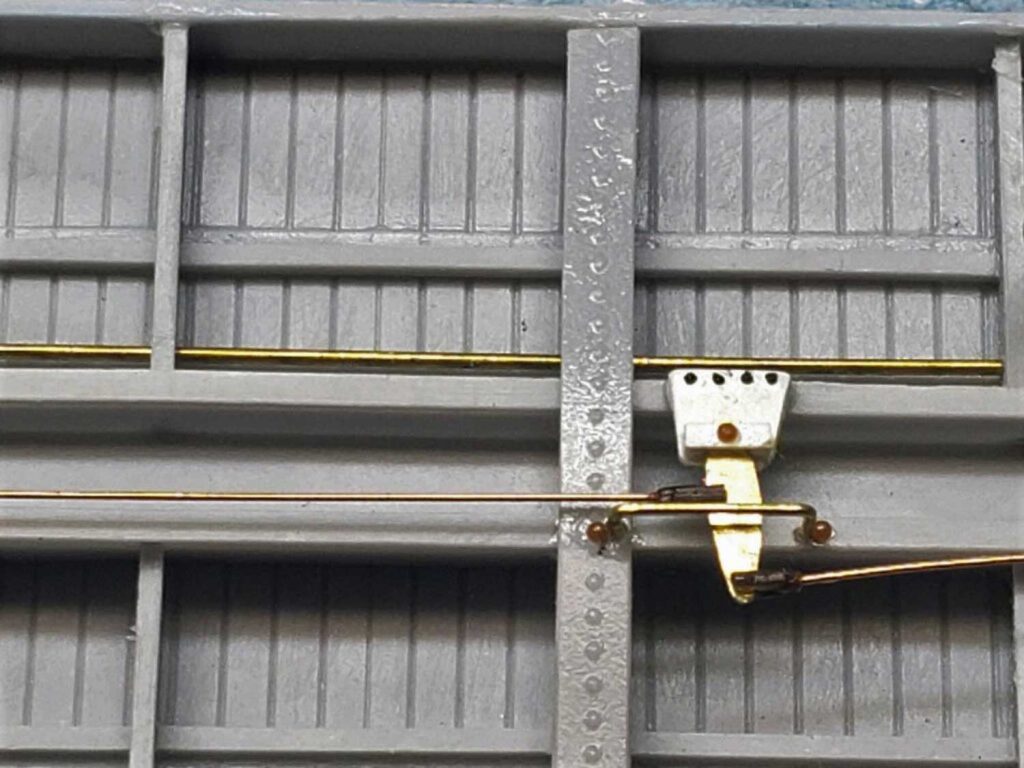
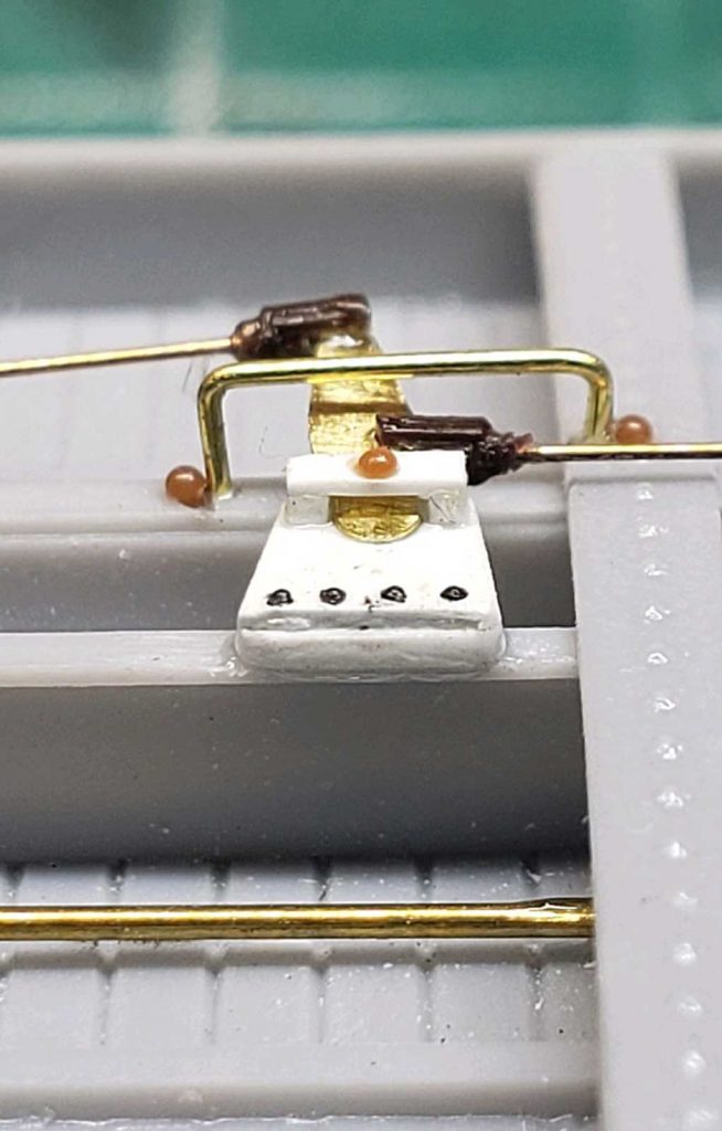
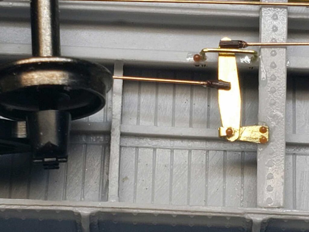
There is one more lever to add near the B end of the car. It’s a little more complex as the support bracket hangs off of the crossbearer. The position of the bracket was marked on the crossbearer and a flat spot was filed for the bracket.
The bracket was fashioned from a piece of 0.005” sheet brass with the end folded over to allow the lever to be cradled within. The bracket was glued to the crossbearer and the lever was glued to the bracket. The lever is a Yarmouth product, clevises are Grandt Line turnbuckles cut in half, the rivet heads are Tichy, and the rods are 0.010-inch diameter phosphor bronze wire. The lever hanger is 0.010-inch diameter bent to follow the drawing.
The other group members did not include any brass parts but used layered thin styrene to create the A and B lever support brackets.
The retainer line was not modeled. Drawings indicated this line starts at the brake wheel then quickly moves to the outside edge of the car. Once it is past the drop doors, the line heads over to the control valve. See the overall drawing of the AB brake system on the RCW Kit Extras page.
The next installment will cover the group efforts on the car body details.
Thanks to Jerry Hamsmith and his Gondola Group for this alternative AB brake system installation. The adventure will continue soon with another part of this NYC gondola kit build.
Questions and comments can be posted below. Please follow the instructions so your comment can be posted. All comments are reviewed and approved before they appear. To subscribe to this blog, add your email address to the function at the bottom of the right column on the main page. Share the blog link with other model railroaders.


Great Work!
Bravo!
Excellent. Thanks for sharing your fine work.
Nicely Done! Very interesting Brake arrangement.
Like the use of brass and harvested rivets to model.
Thanks for sharing your techniques
George Toman
Jerry
That’s beautiful workmanship