Bill Darnaby sent tips on building resin tank car kits. Here are Bill’s notes and photos.
In this essay I will describe how I assembled the Resin Car Works ACF insulated tank car kit. This is not meant to be a regurgitation of the published instructions but, rather, to describe some different approaches and, maybe, helpful hints.
The kit is well designed and is easier to assemble than many of the resin tank cars I have done over the years. The hardest part of any resin tank car is building up and detailing the underframe and this one is no exception. However, it is much improved over the many piece part underframes of the kits offered years ago. Perhaps is it beyond practical casting techniques but I would have liked to see the running boards cast with the frame.

Always inspect resin tank car frames as they are easily warped during removal from the mold and curing. I found the end sills to be bowed with the corners drooping down. Conditions like this are easily rectified with the careful application of a little heat. I heat a flat surface to 250 degrees in the oven. The part itself never goes into the oven as control of dimensions gets iffy. After the flat surface reaches temperature it is removed from the oven and the part, whatever it is, is placed on it. The part will absorb heat from the surface and become flexible. In this case, weights are used to force the end sills straight as everything cools. This works for just about any resin part that is warped. I have straightened seriously bowed flat kit sides by placing them on such a hot surface and using a straight edge to bring them into alignment.
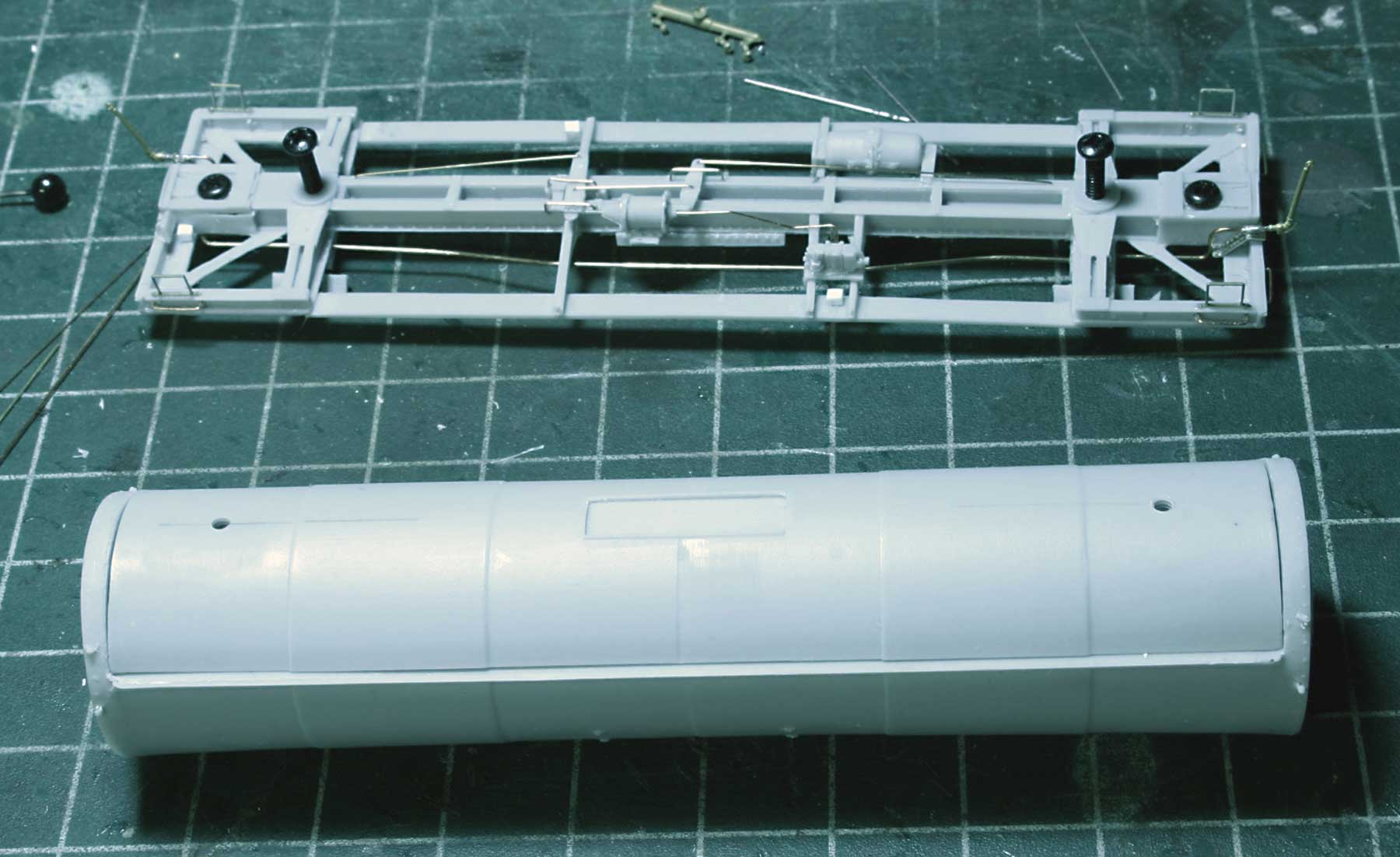
While the frame is a loose part I like to drill all of the holes including those for grabs and brake lever hangers. The draft gear has been drilled and tapped but the bolster was only drilled out for the tap drill. It is important to fix the attachment of the frame to the tank as early in the process as possible as the parts are easiest to handle with no details on them and getting a straight and square orientation is much easier. The tank bottom has a rectangle cast into it that engages the frame to assure a centered and straight orientation with the frame. The tank saddles have been added and sanded to fit the curvature of the tank by wrapping sand paper around the tank and running the tank back and forth in the saddles.
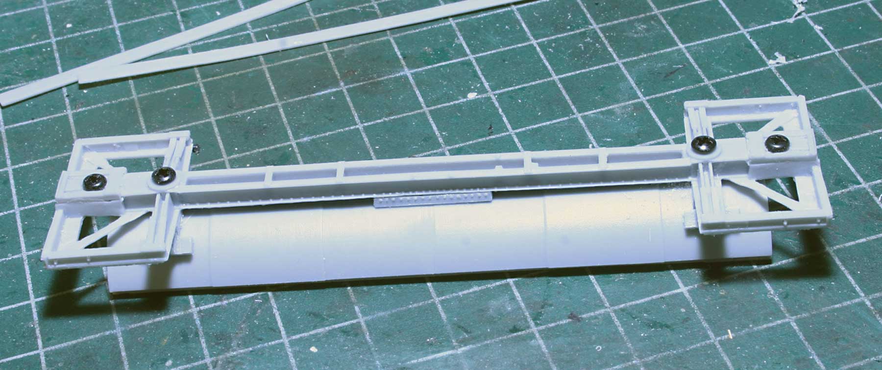
Locate the tank bottom on the frame noting that the tank bottom rectangle no longer touches the frame because of the addition of the saddles. The frame can be defected so the rectangle can be engaged with the frame for positioning. When satisfied with the tank bottom position, drill out the tank bottom through the bolster holes with the tap drill. Then tap the bolsters and tank together. They are shown here fastened together with half inch 2-56 truck screws. I added the center anchor rivet strips at this point because it was convenient. They are attached to the frame with CA but not to the tank bottom so the tank bottom is completely removable at this point.
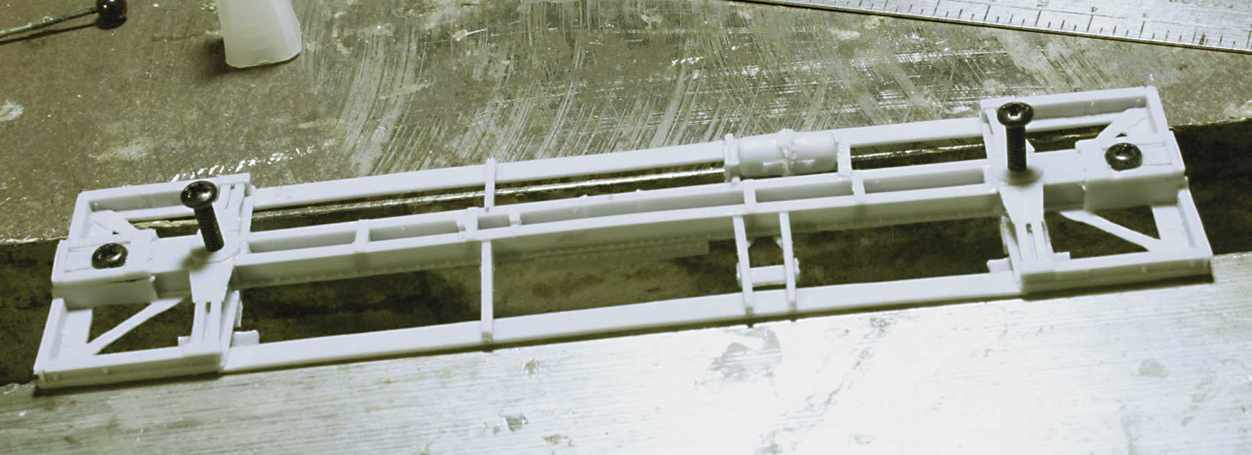
As shown here, I supported the frame between two flat surfaces to insure that the running boards were straight for the application of the running board supports and brake hardware. The running board supports face the ends of the car except for the pair that support the valve and which face each other.
Note that I screwed up and placed the valve support on the wrong side, top instead of bottom, of the two running board supports. I did not find this until later in the process. This is the hazard of the prototype drawings which always show the placement of these parts from the top looking down. The classic example of this error is the Athearn blue box boxcar and its brake arrangement. Note that the brake arrangement for the car I am building is the AB2 version.
At this point the frame details have been added including the sill steps, piping and brake rigging. I do not take the trouble to add clevises for the brake rods as they really cannot be seen from the side even on the upper level of my railroad. Instead, I just drill holes in the levers for wire.
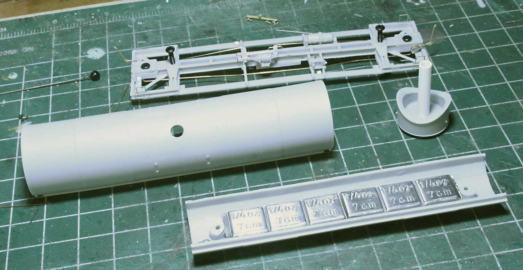
It is time for the tank assembly. I have always used quarter ounce stick-on weights for my resin cars with six per car. They have been added at this point prior to tank assembly. The dome has been sanded for a good fit with the tank and the piece of 3/16-inch styrene tube for location has been added. All of the dome and tank grab holes have been drilled at this point.
A test fit of the tank bottom to the tank revealed a sizable gap between the tank bottom and tank ends. The tank ends had apparently splayed out during removal from the mold and curing. This was confirmed by placing a machinist’s square on the top of the tank. Note that on the frame I finally got the valve support in the correct place and little drilled out blocks of styrene for the placards have been added to the underside of the running board.
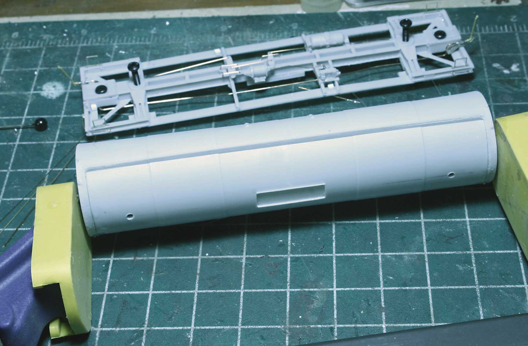
I corrected the end gaps by placing a clamp on the ends and applying CA. The clamp is one of those grips with soft jaws. Doing this created a larger gap between the tank bottom and tank below the rib. After the ends were set I applied CA to the side gap and held the halves together with my fingers. Any remaining gap was filled with canopy cement.
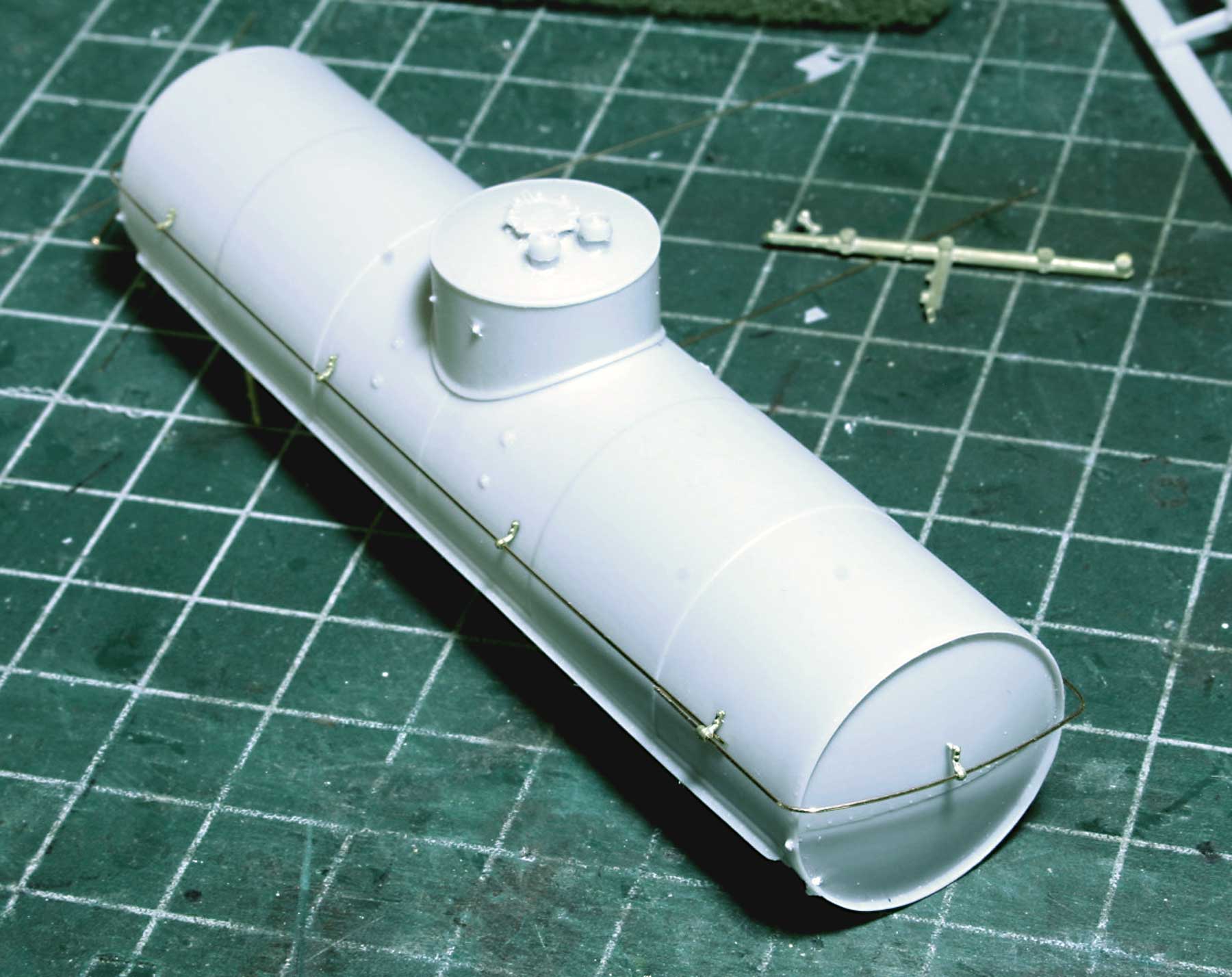
The published instructions say that the handrail bracket dimples in the tank need to be repositioned. I did not find this to be the case because the dimples placed the handrail at the correct distance above the running boards per the prototype drawings.
Now, because of the contour of the ends the end brackets are never in the suggested location. To get around this I leave the end brackets loose during the handrail fabrication and then let the brackets locate themselves. As seen in the photo the bracket pin is resting against the tank end just where it wants to be. I just mark that location, drill the hole for the bracket and push the bracket in place. This applies for every resin tank car I have ever assembled.
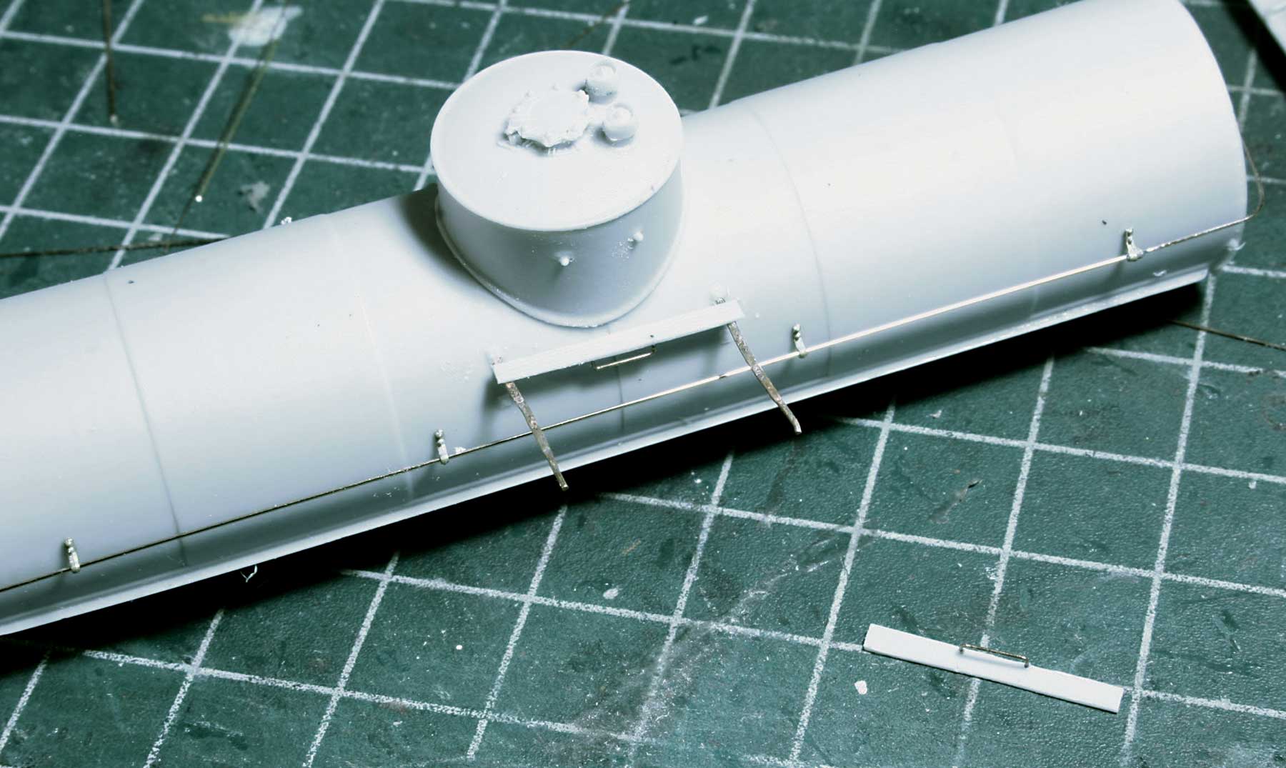
I followed the instructions for installing the dome platforms and consider them to be the best method for their installation I have found. The photo shows the A-Line still steps in position after they have been annealed with a cigarette lighter and straightened. I trimmed them and bent them down to reach the lower cast on pads. This is the most robust dome platform construction I have found. Do not forget to add the grabs to the bottoms of the platforms if required.

After installing the remaining details to the tank, it is ready for final attachment to the frame. Pay attention to the orientation of the dome vents with the B end of the car. It varies. I started going by the prototype plans and just at the last minute I looked at the prototype photo of the car I was doing and realized it was different. For my car the vents go to the B end.
I used the truck screws to attach the tank to the frame. After a final check for squareness, etc., I wicked CA between the tank and saddle blocks and center anchor rivet strips for the permanent attachment.
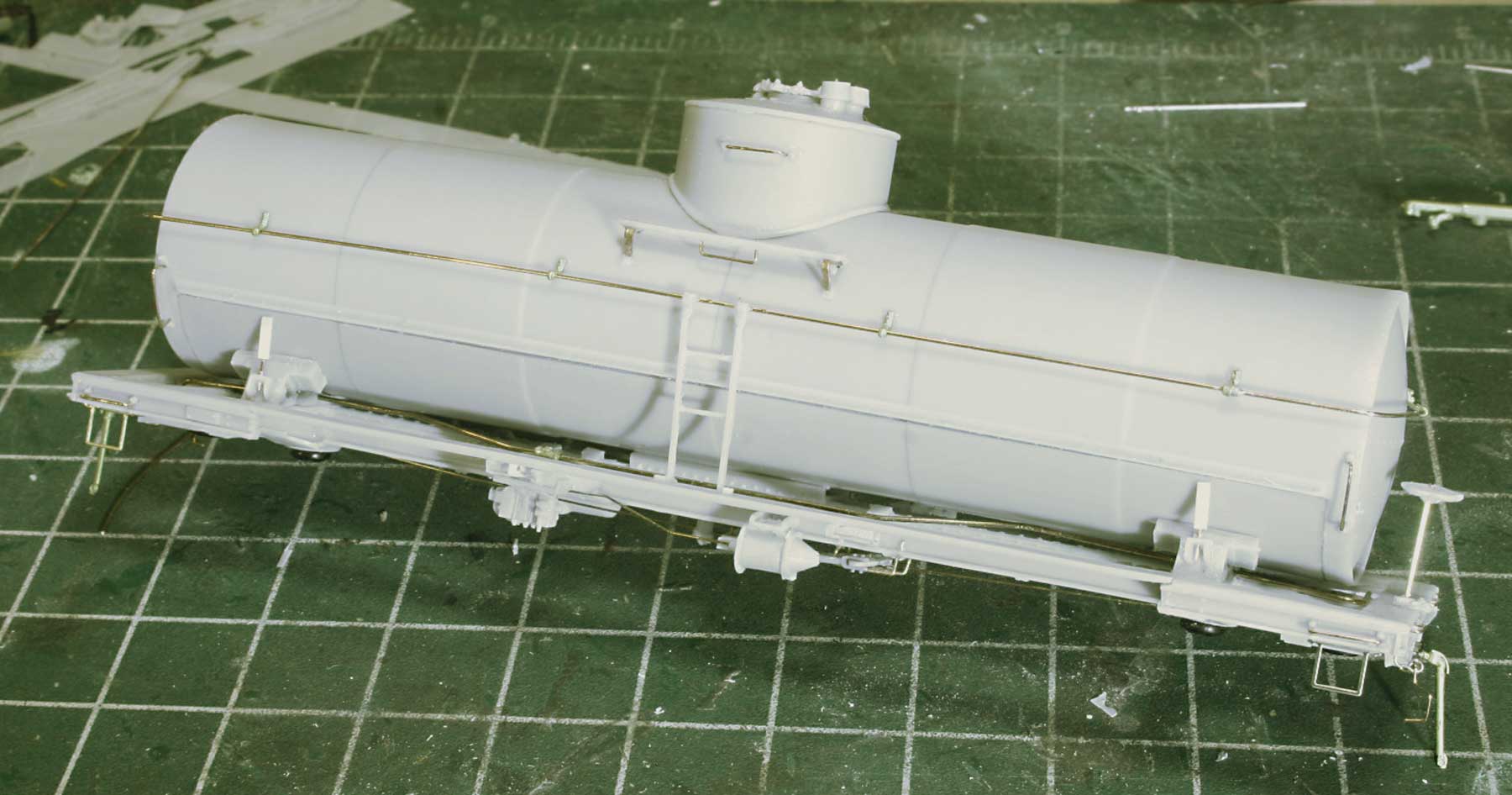
The car is ready for painting. The final details have been added including the tank bands and brake wheel. The placards have been left off so they can be painted separately to take advantage of their fold down over the decal placard feature. After application of the placard decals the placards will be added to the car by inserting them into the little blocks under the running boards.
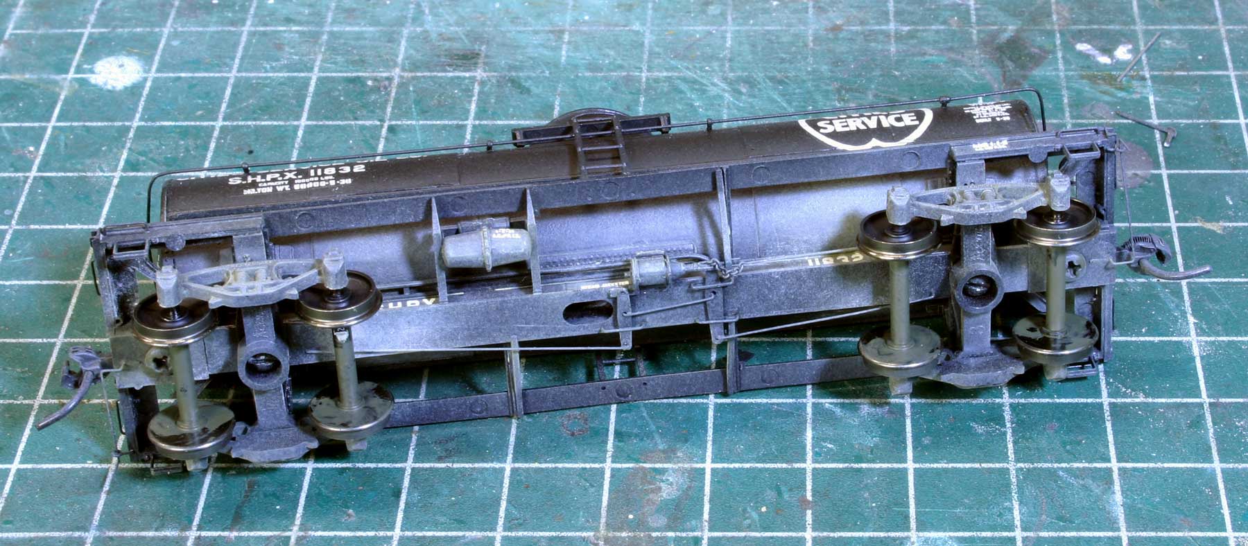
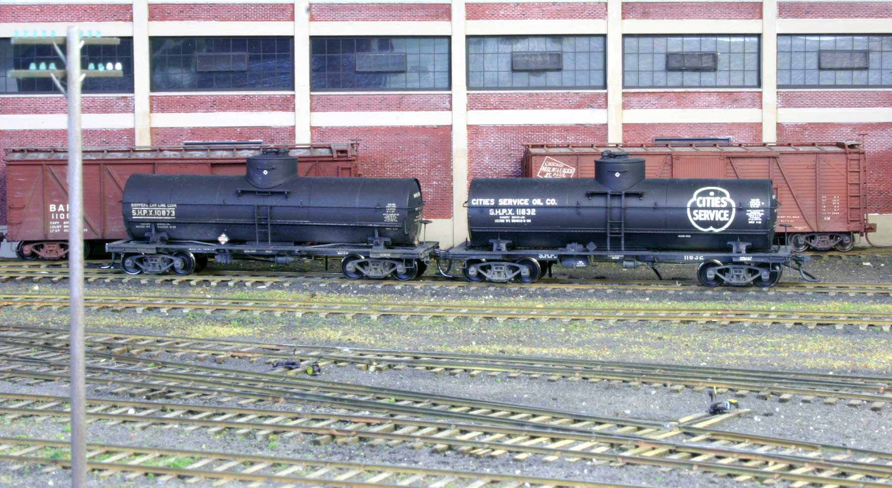
I had acquired a preproduction tank body some time before the kit was released and found that a fair representation of the car can be made by mating the tank with an Intermountain 10,000 gallon, Type 27 underframe. Obviously, the underframe details are not all correct but the brake details are where they should be. It is a compromise and should not dissuade the modeler from building and detailing the kit underframe.
Many thanks to Bill Darnaby for sharing some great tips on building resin tank car kits. We better all get to work on our kit stash!
Questions and comments can be posted below. Please follow the instructions so your comment can be posted. All comments are reviewed and approved before they appear. To subscribe to this blog, enter your info for a comment and check the last box to notify of new posts by email. Share the blog link with other model railroaders.
Very nicely done!
Fine build. The heat tip, taking heated item out of oven, a great tip.
Thanks for sharing your build experiences. I really appreciate it when you, George, or somebody else provides their insights and techniques before I build my kits. I’m glad I left this one in the stash until you wrote this blog post. Precision work as always.
Bill, Those are some great tips on assembling your ACF RCW Tank kit.
Thanks for sharing
George Toman