Pete Hall sent an interesting modeling project. Here’s his story.
Many railroads used coal as fuel for their steam engines, but the Southern Pacific did not – they used oil. Oil was plentiful in early California, and refiners were only too eager to rid themselves of the stuff at the bottom of the barrel, called Bunker C.
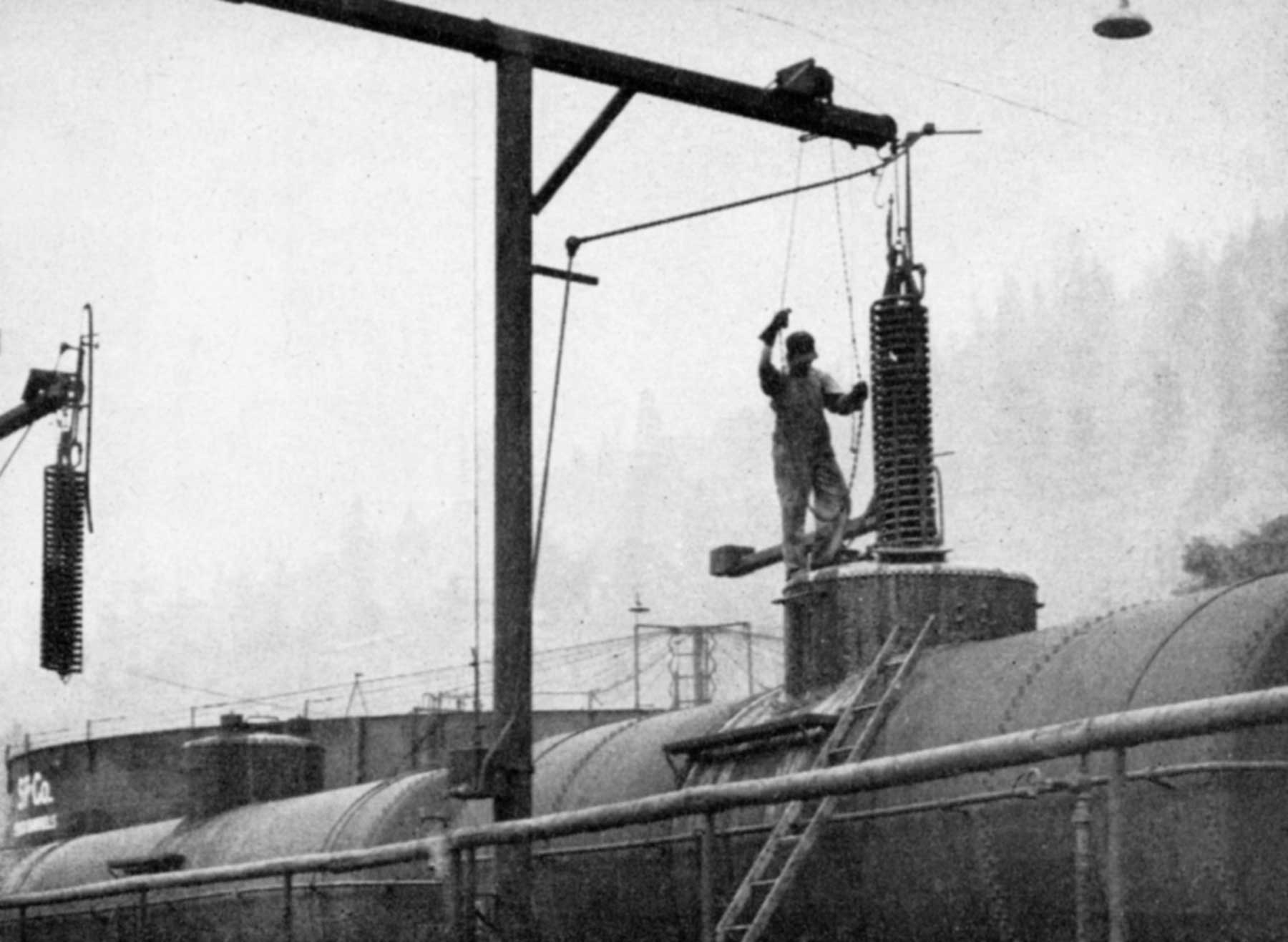
It turns out the stuff was ideal as fuel for steam locomotives. It had plenty of hydrocarbon energy but had one disadvantage – it was thick and heavy. The SP used steam heater coils that were lowered into tank cars so the Bunker C would flow. A lot of later tank cars had internal heaters, but these external heater fixtures could be seen in many locations where the SP had engine fueling facilities, particularly in California. The lead image illustrates the prototype operation.
The SP had to heat their tenders, too, to keep the fuel flowing, and the rule-of-thumb for SP firemen was that if the temperature of the oil tank was uncomfortably warm when you held the back of your hand against the metal, it was just right for the oil.
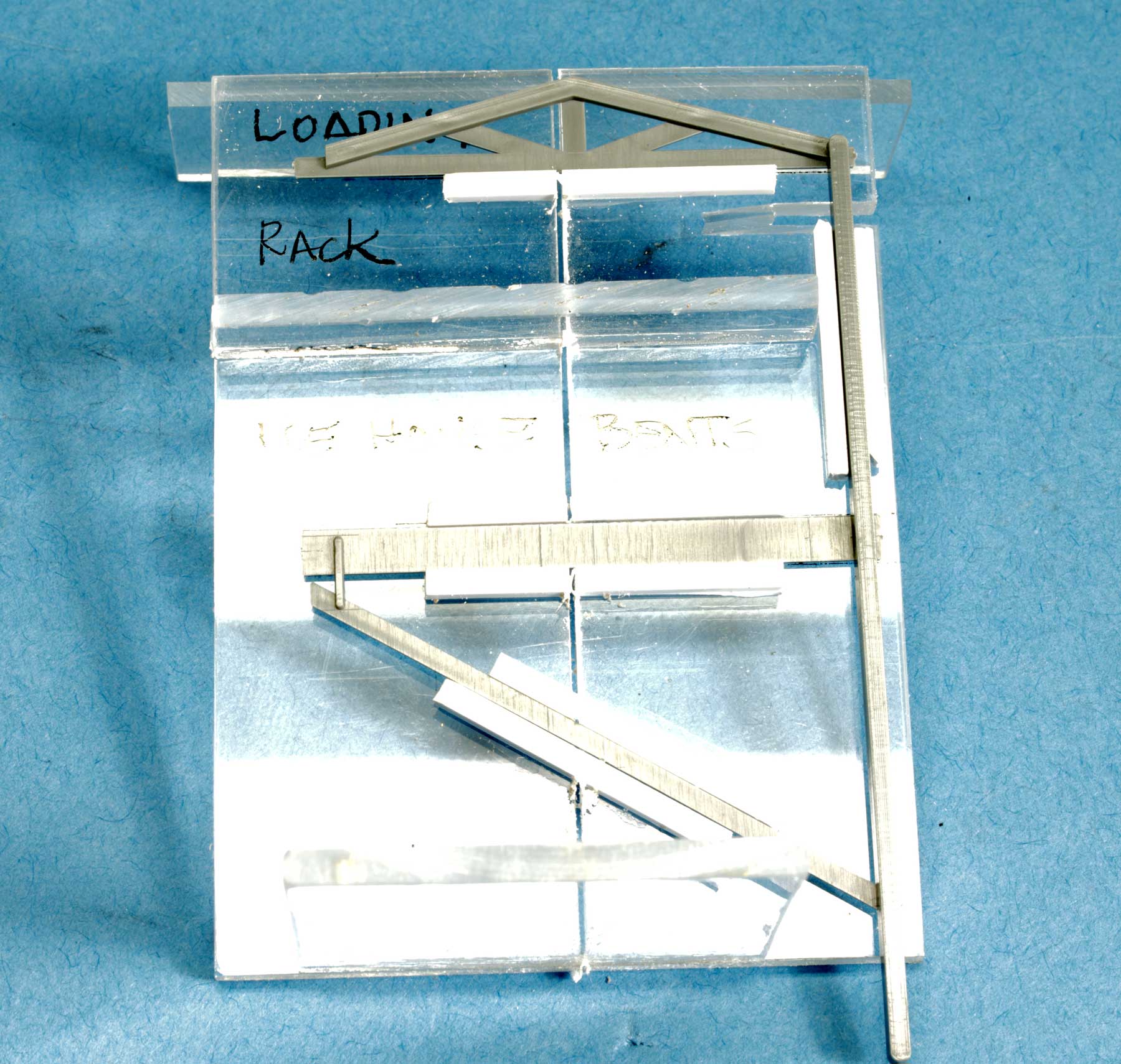
I decided a siding adjacent to a large Bunker C fuel tank needed an unloading rack. The more I thought about it, the more it seemed to be an ideal scrap-box project. Everything I needed came from a kit or collection of materials already at hand. The SP may never have had a platform like this one, but then again, maybe they did.
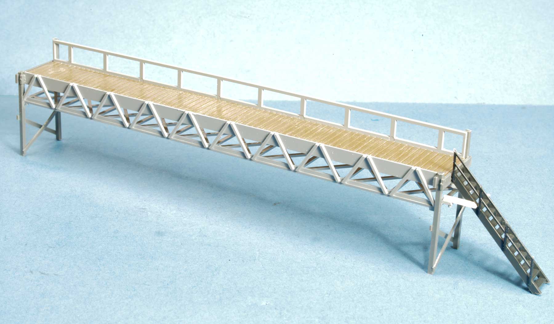
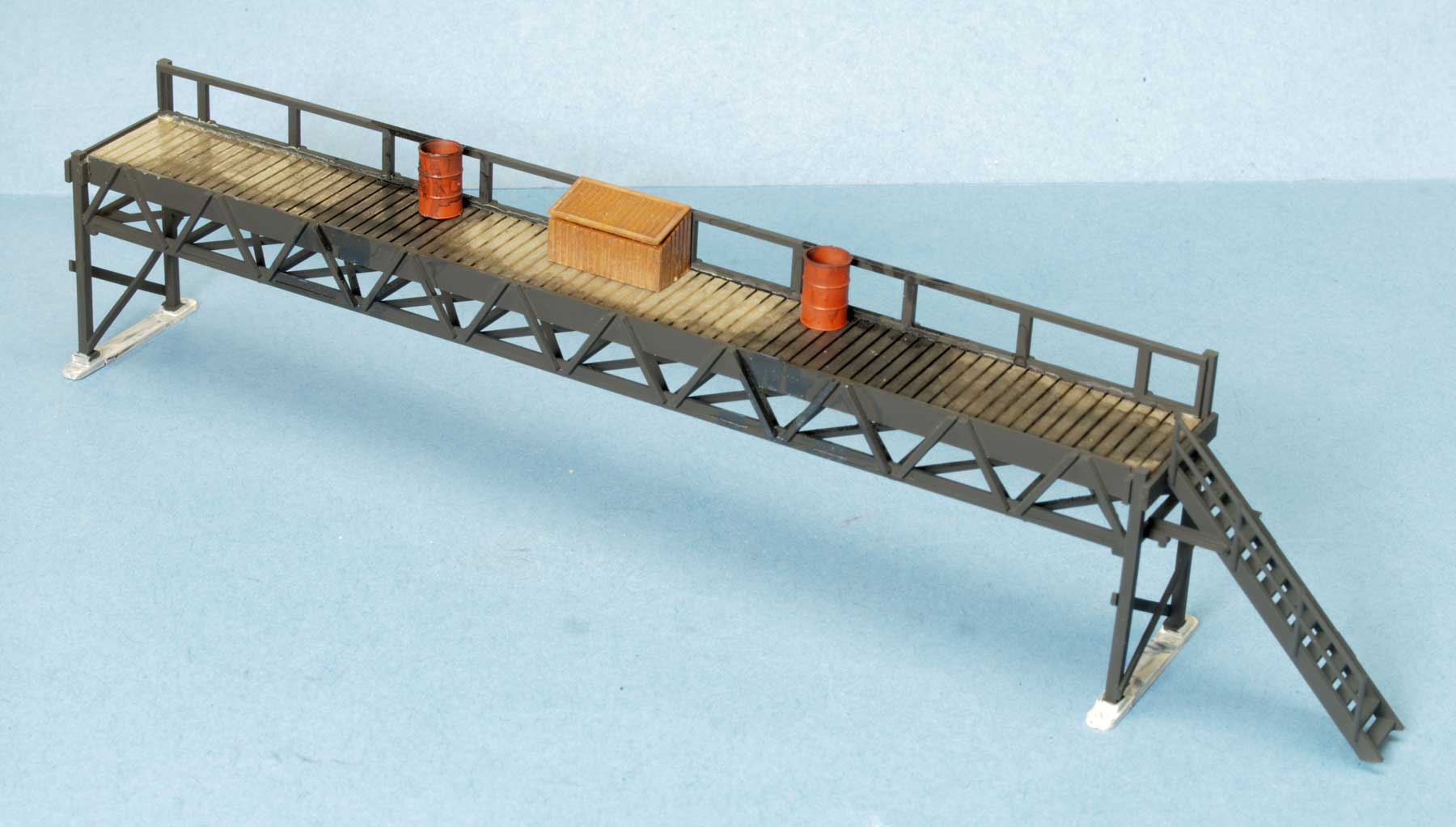
The first step was to build the platform. I wanted something that would put the worker at about the same height as the dome walkway on the side of a tank car. That would give good access to the dome cover and manhole at the top. Since many SP tank cars had dome walkways on only one side, there was no guarantee that the tank car would arrive with the walkway on the platform side.
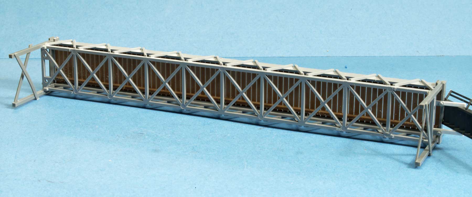
Underneath the platform was a duckboard with unloading hoses that connected to the main unloading valve at the bottom of the car, so the platform had to span about 1-1/2 tank cars without impediments to the workers beneath. It seemed that a trestle arrangement would do the job. I used parts from the Walthers Modern Conveyor 933-3518 to form the trestle, with the handrail on one long side cut off.
I attached the trestle to ends cut from CMA/Tichy Ice House bents and grafted on a Plastruct staircase with a Central Valley handrail. A couple of strips of 0.060-inch styrene angle holds the staircase in place. The working deck was made from Walthers fencing cut to a width to match the trestle. Another strip of Walthers fencing became the duckboards underneath the platform.
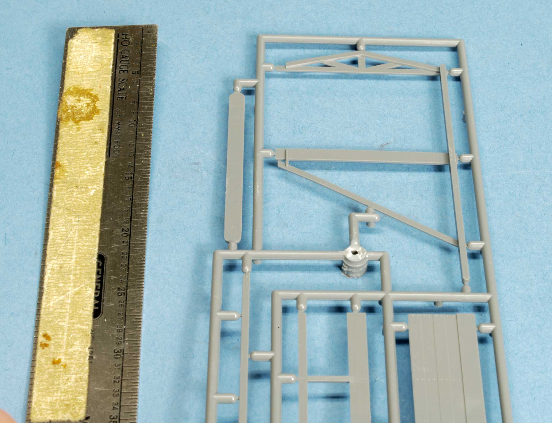
The ends were a little tricky to make. The CMA bents are about twice as wide as needed. I glued two of them are glued together to form a bent for the icing platform.
I built a jig in Plexiglas to cut the four ends uniformly. The legs were cut off at 10 feet. The top halves were also too tall, so I sliced off the upper columns even with the front girder and the back handrail. However, the middle braces are at exactly the right height to place the working platform just about even with the tank car walkway.
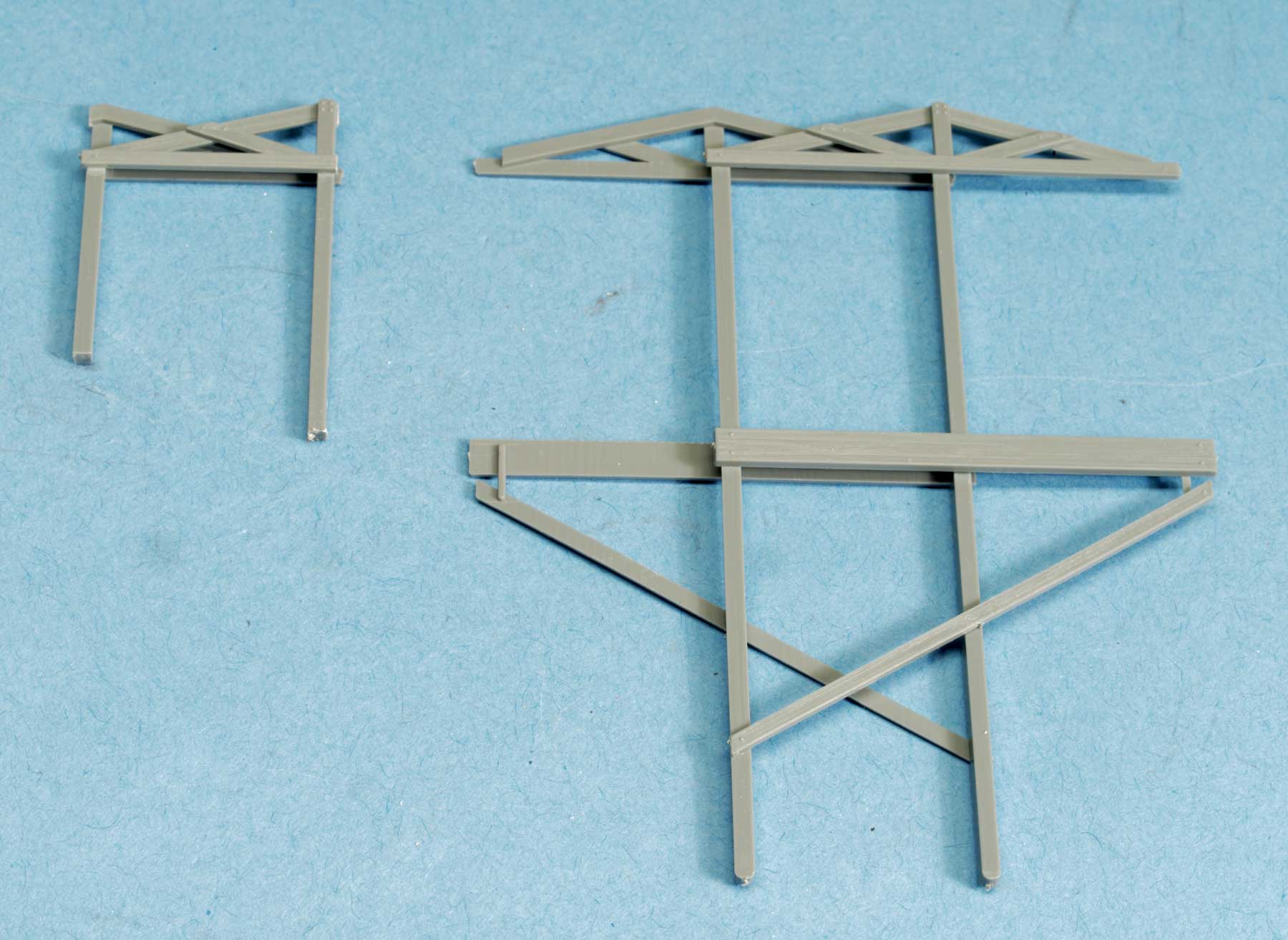
The triangular cross-bracing at the top of the bent makes a nice natural spacer to line up the two halves at exactly the right distance apart before removing them. Sometimes you just get lucky.
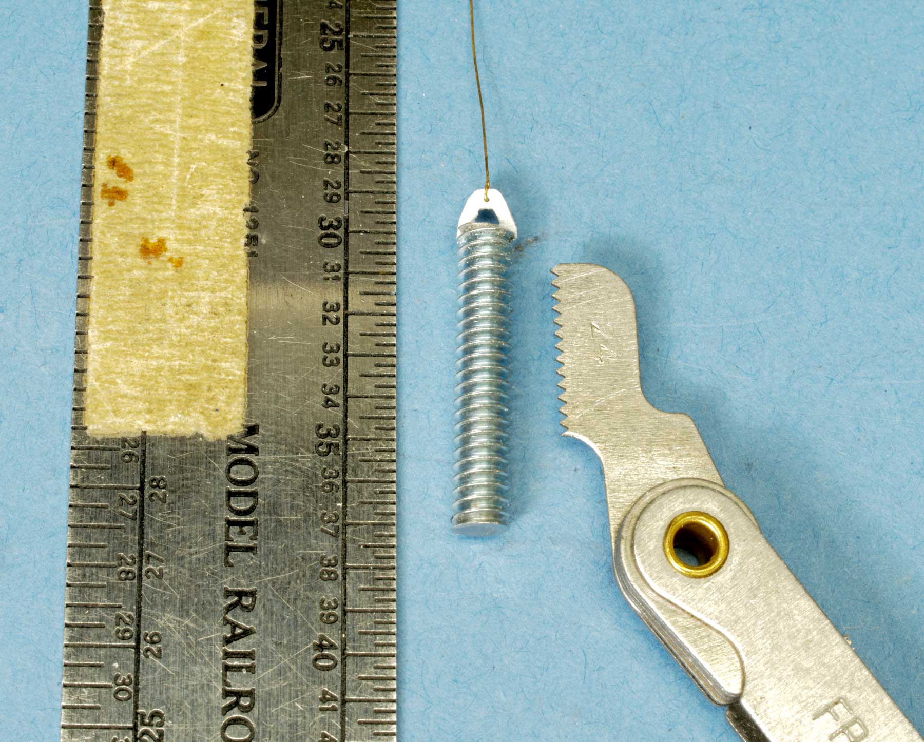
The heater assembly was a little harder. I had no plans for the heater or gantry. I scaled the measurements based on the man working to lower the heater into the car, as seen in the prototype photo that leads this post. Examination of the heater led to the conclusion that it’s a helix – a coil in the shape of a screw. Comparing it to the prototype image I felt a #10-24 machine screw is the right size to simulate the coil.
I cut a suitable screw into two, seven-foot lengths with a Dremel cut-off disc, then cut a slot into one end of each one. I glued a piece of 0.030-inch styrene into the slot, which I carved to look like the triangular brace holding the heater to the wire suspending it.
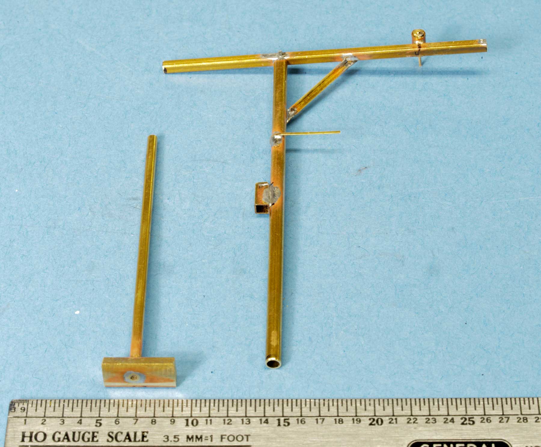
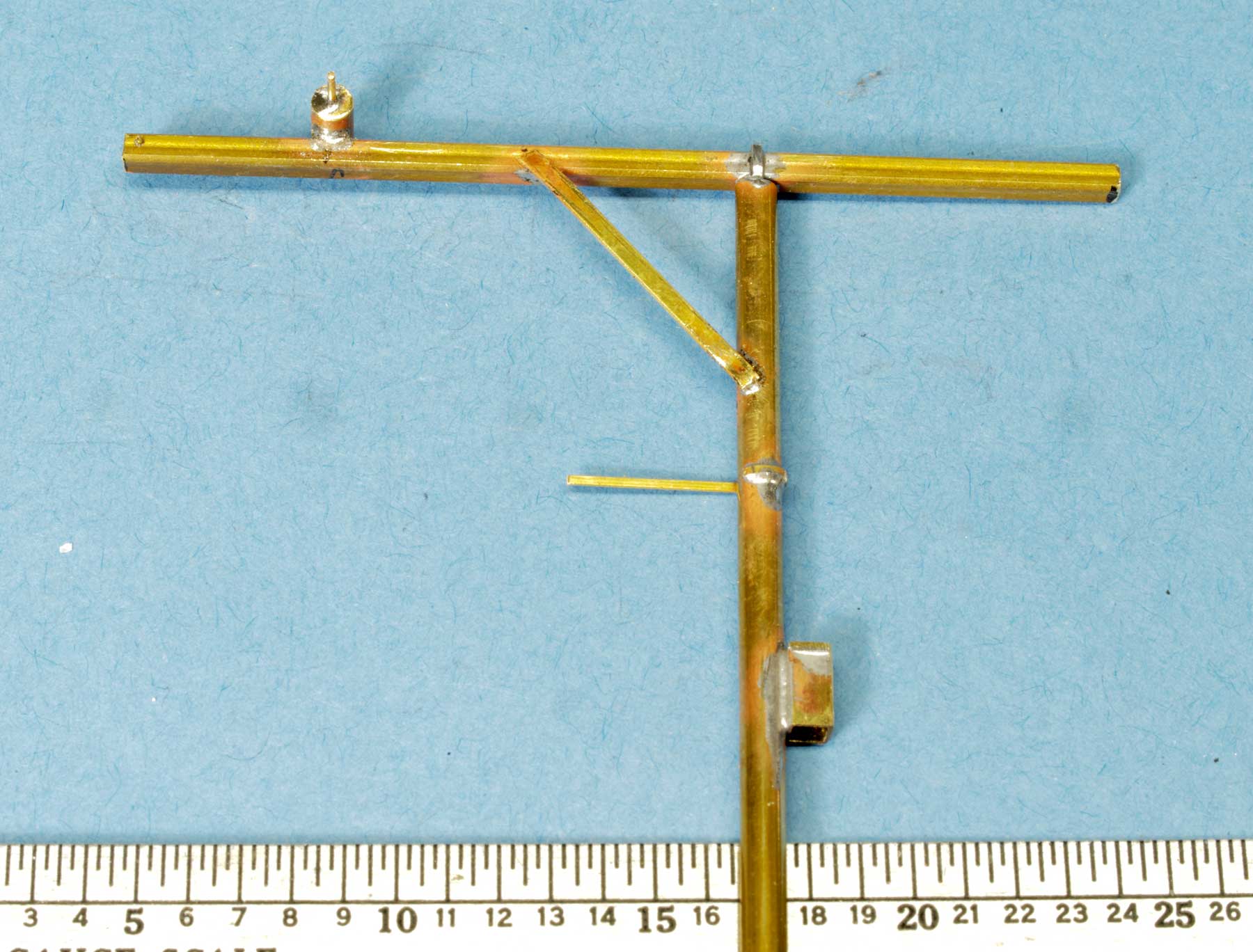
Next, I soldered together a few pieces of brass from the supply drawer into a gantry with an angle brace, a flat bar to hold the steam pipe, and a box. I’m not sure what the box does, but it’s in the photo, so I needed it.
The top bar is 0.096-inch square box strip, and the vertical piece is 0.125-inch diameter tube. I looped a piece of 0.010 x 0.030-inch brass strip over the box and into the tube to act as a brace during soldering. The strip fills the gap on either side of the box. The tube fits concentrically over a length of 0.063-inch tubing which is soldered to a piece of bar stock used as a concrete base.
Slipping one tube over the other gives the structure stability while allowing the gantry to rotate. There is a chain hoist near the end of the horizontal arm, which I made by soldering together several tubes and cutting them into two pieces to form the hoist cover. The advantage to using concentric tubes is that I could solder a piece of round wire through the center to act as the axle of the hoist pulley.
Once I had the hoist in place, I cut a slot in the top at the end of the arm, where the wire rope pulley would go. I used a piece of brass round bar stock to create a pulley with an axle hole in it, drilled a hole in the end of the arm, and soldered an axle through the pulley into the arm. The wire rope to the heater coil will run over this pulley.
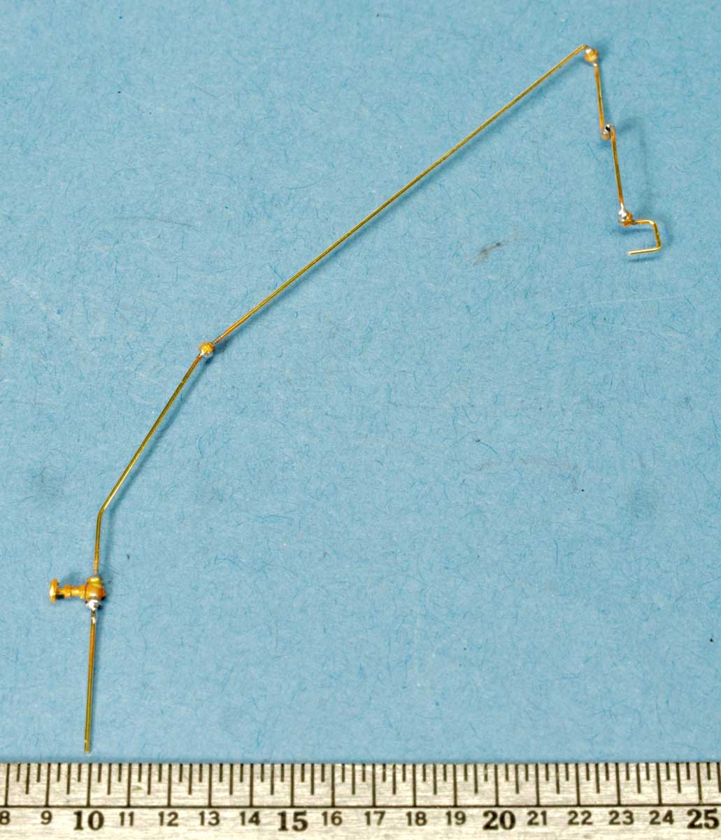
Next, I fashioned the articulated steam pipe from 0.020-inch” wire and Kemtron (now Precision Scale) #832 unions. It took a few tries to get the joints right, but I think it works. I added a globe valve to the line below the box to serve as a control for the steam flow to the heater.
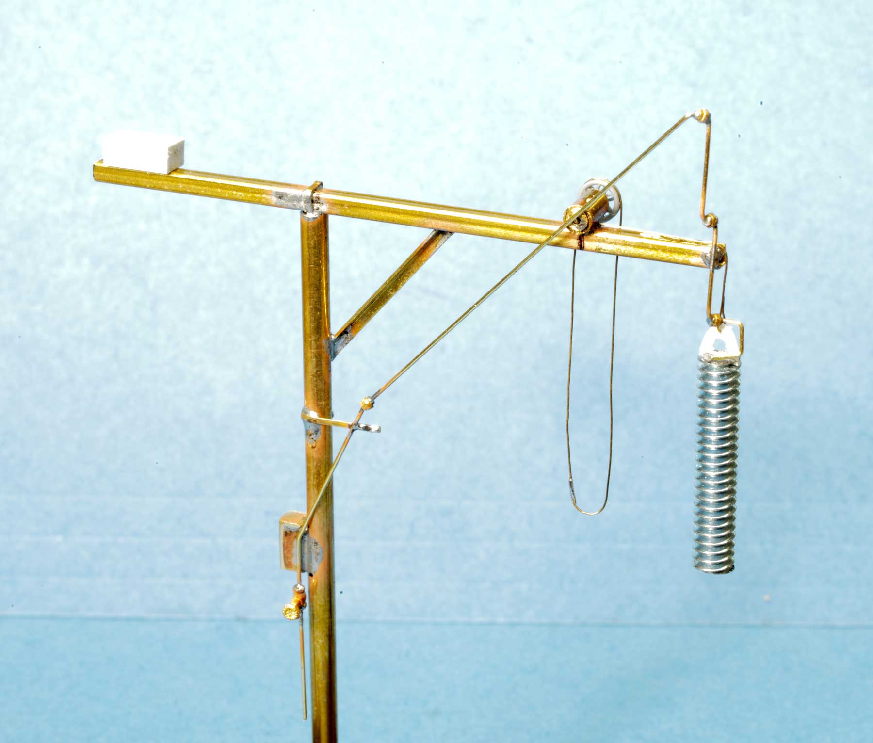
I soldered the steam pipe to the gantry next. I glued two Tichy 3013 AB brake handbrake wheels (part 33) together on the axle to form the two halves of the hoist pulley. A length of 0.009-inch fine wire was looped over the pulley to represent the chain that works the hoist. Photos seemed to show that the SP hoists had the pulley on either side of the hoist motor and on this model, they fit better on the opposite side of the steam line.
The gantry arm had a counterweight at the far end, which I represented using a 0.30-inch long piece of 0.125 x 0.0156-inch styrene strip glued to the top. The final step was to run the heater coil support wire over the pulley at the end of the wire and glue it in place. The end of the steam line was then glued with thick CA to the top of the heater coil. These assemblies will stand behind the platform.

Beneath the platform is the oil line that is connected by large hoses to the bottom outflow valves of the tank cars. This oil line gets hot when the oil flows through it then cools when tank cars are removed, It needs to rest on rollers so it could expand and contract. I made rollers from a length of brass rod. I turned the rod in a lathe while holding a round file against it. I made two rollers and drilled out the centers so to insert an axle. I made two U-shaped pieces of 0.015 x 0.060-inch brass strip, drilled holes for the axles, and soldered the two roller assemblies together. These were painted silver.
Some plastic sprue was used for the oil line. I painted it and attached it to the rollers. I drilled holes in the two upward sprue legs and inserted hoses; these are lengths of 14-gauge wire painted Vallejo Dark Rubber with a couple of brass flanges on each end. The sprue legs had smaller plastic stems so I found two more brake wheels in the parts box, drilled out their centers, and placed them over the stems as valve controls. The legs simulate valves, so they are painted silver.
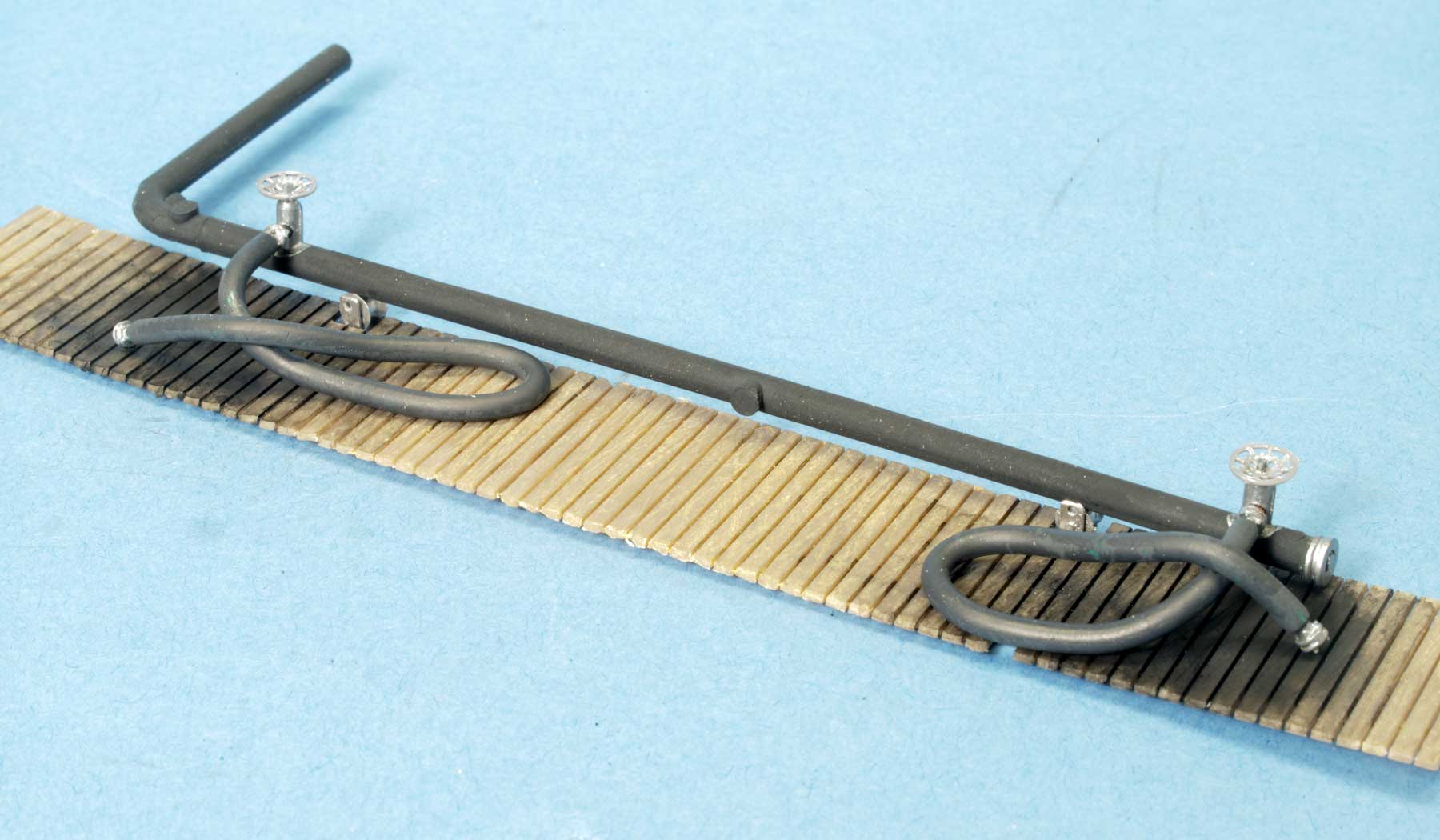
This assembly was placed onto a length of Walthers fencing that was painted to resemble old wood and weathered with black washes to simulate spills. I used a little Pledge Future Floor Wax (aka Pledge Revive It Floor Gloss), which dries glossy to simulate the oily surface of the spills.
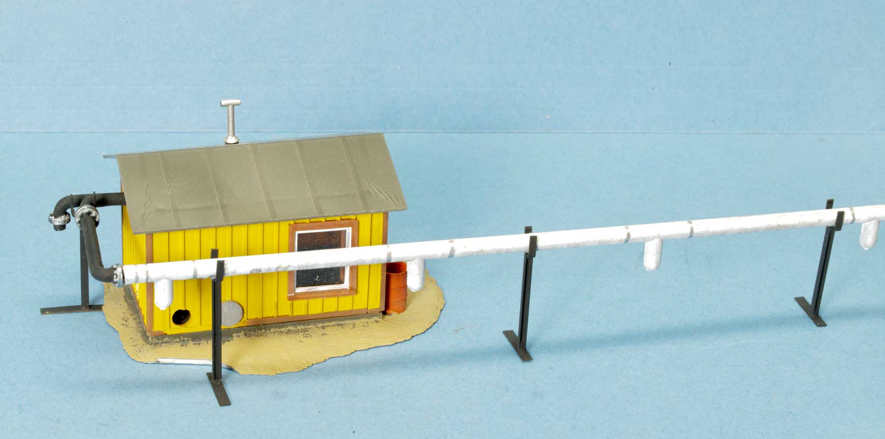
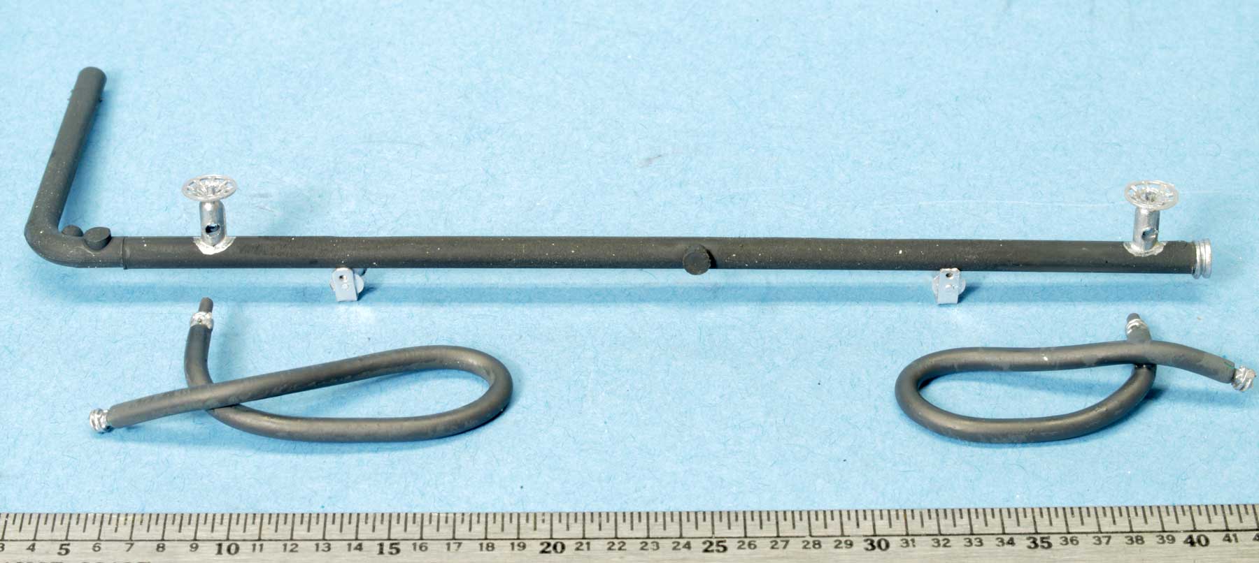
A large steam pipe runs horizontally behind the platform and supplies steam for the heater coil. I simulated that pipe with another length of old plastic sprue, painted flat white. When it was dry, I inserted the sprue into the lathe and turned it very slowly. I applied a silver paint pen to the sprue while it was turning to simulate the steel bands used to secure the white insulation around the pipe.
The pipe is supported by stanchions made of 0.015 x 0.060-inch brass strip U-shaped yokes that are soldered to lengths of rail. The sprue had four legs that work well as steam line valve connections for both the heater coils and the steam hoses that were used with tank cars equipped with internal steam heaters.
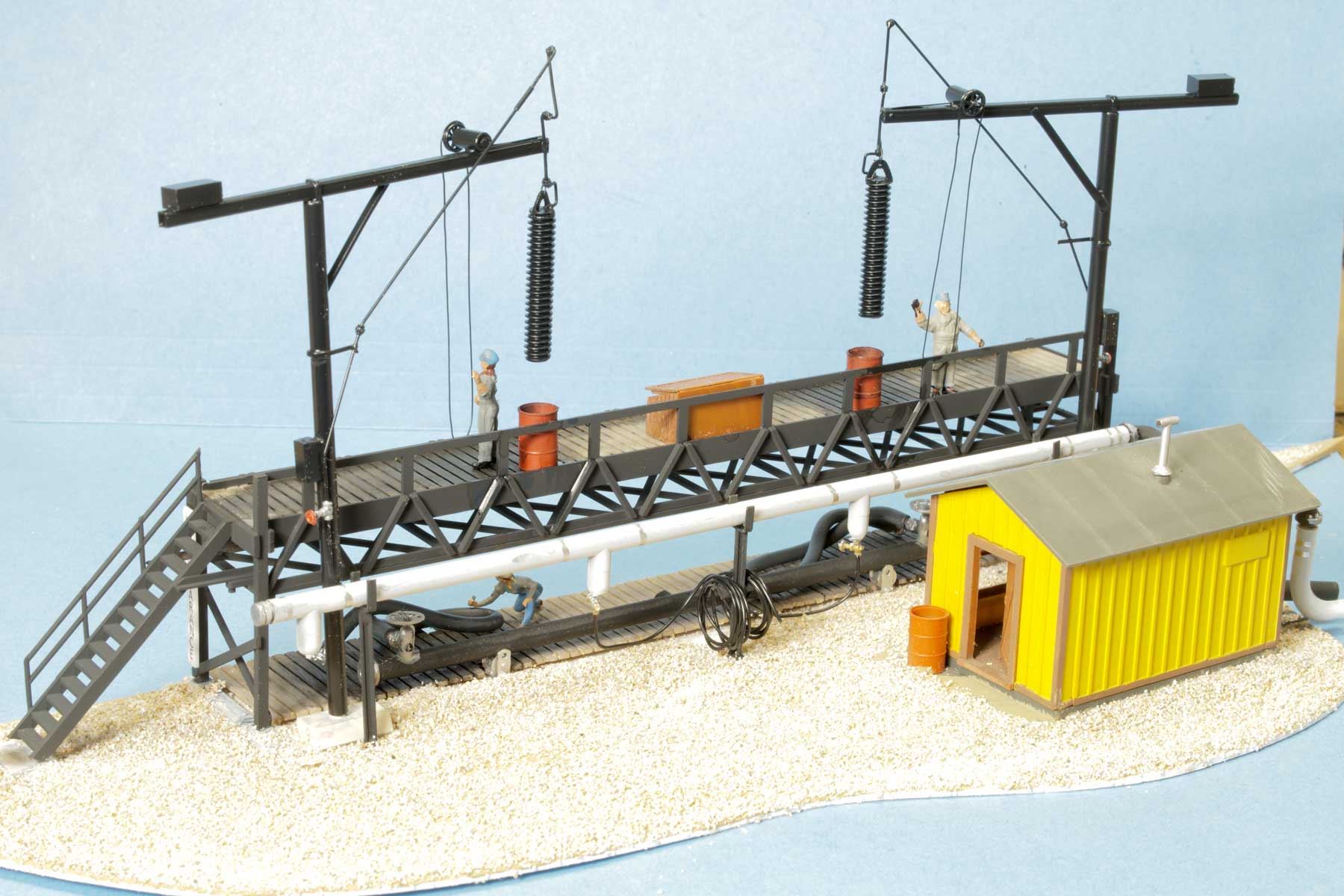
I used a Precision Scale O scale part (#4402) to connect the steam line to the control house. I find that O scale parts are good for large piping in HO scale. This part (actually a Cross-Over Connection, Steam Supply for a C&O J-2) has a yoke that happened to be in the right place to form both the main line and the steam line that goes to the oil storage tank. The flanges are painted silver, and the part fits into a hole in the back wall of the control house. The control house has been on the layout so long, I’ve forgotten its origin. The side wall has a hole for the hot oil intake pipe, as well as one in the back wall for the outlet to the tank. This will be hard to see when the platform is installed,
Now the assemblies are ready to come together. The entire model sits on a slab of 0.060-inch styrene that supports the scene for placement onto the layout. I painted the slab my former favorite color, Floquil Earth, and glued the house, the steam line and the oil line in place. I added the smaller steam hoses using coils of Miniatronix 1.5-volt bulb wire. I have a lot of it in the scrap box, as most locomotive lighting installations only require a couple of inches of wire. Each line is looped over a hose rack, then through a brass valve and up into the drop from the steam line.
I narrowed the original CMA leg bases and then glued the legs into them; the location of the bases on the styrene were marked in place. Then I painted the platform and weathered it where the heaters would drip Bunker C onto the platform as they were being rotated into and out of the tank cars. I added two old oil drums to catch the drips (not very effective), and a wooden box to hold the various tools needed to open tank car manways and insert the heaters.
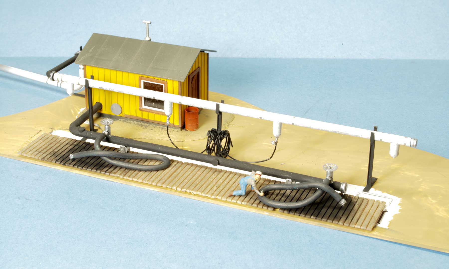
At this point, I add ground cover (ballast) to the scene, leaving a couple of bare spots to attach the platform bases and the oil heater gantry bases, and set the platform in place. Since the platform sits close to the track, I added a “NO CLEARANCE” sign written vertically, on the stairs end of the platform; tank cars are pushed into the spur from this end.
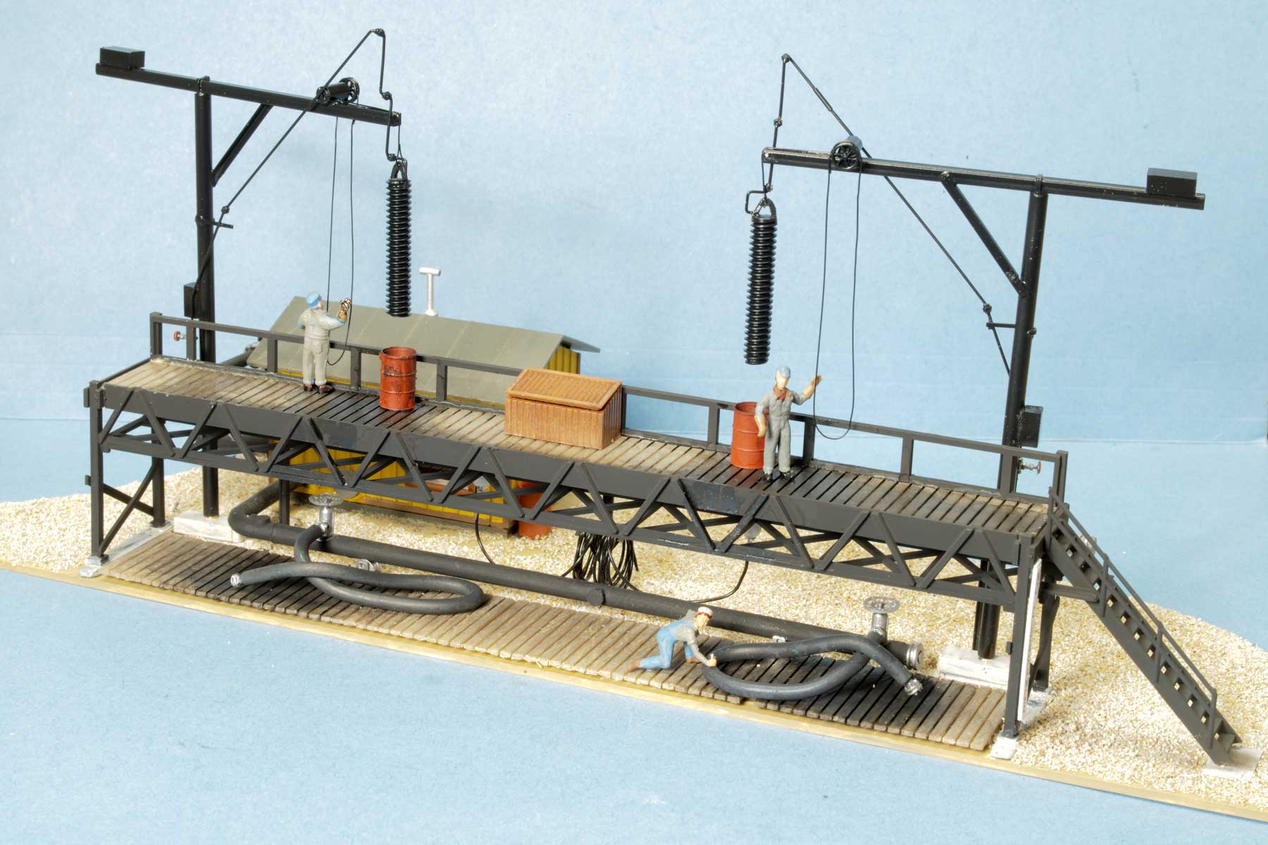
Here’s the final assembly, ready to be installed onto the layout. Most of it was built from pieces already at hand.
Wow! Many thanks to Pete Hall, for sharing his techniques and steps to produce an amazing model.
Questions and comments can be posted below. Please follow the instructions so your comment can be posted. All comments are reviewed and approved before they appear. To subscribe to this blog, add your email address to the function at the bottom of the right column on the main page. Share the blog link with other model railroaders.
Really cool. When I first saw the heater I thought – spring from a pen. I like your use of the bolt.
Thanks for sharing
Mark
Extremely nice work.
The statement “Many railroads used coal as fuel for their steam engines, but the Southern Pacific did not – they used oil.” is incorrect.
SP used coal in New Mexico and some of their AC locomotives, usually thought of as Cab Forwards, were of convention design and used that coal.
That’s true – I should have made that Caveat in the article. As a Coast Division modeler, I get a little myopic!
That is a really neat little scene. Nice work!
Really beautiful and inspiring piece of work!
While I have absolutely no use whatsoever for a structure like this, I loved reading about the way you made some of the parts….even tho some of the techniques are beyond the range of my talents. That is a model to be proud of. Thank you for sharing your methods.