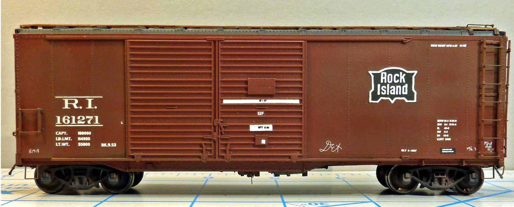
George Toman shared details on building a Rock Island car from the 161000-161349 car series. The model is inspired by the 2015 Prototype Rails Shake-n-Take project. Here’s George with the details.
When I saw a photo of the Rock Island 40-foot automobile boxcar from the 2015 Prototype Rails I knew that I had to try to build one. The original instructions can be found on the Shake-n-Take discussion group. You must sign up as a member to view and download.
The prototype was built by AC&F in April 1937 with square cornerposts and dreadnaught ends. I was fortunate to acquire some of the resin parts and body for this build. I did not use the resin underframe, opting to build one from scratch for a higher level of detail.
Car Ends
The starting point for this build is a newer MDC/Roundhouse/Athearn tooling of a double door boxcar. The car ends will need to be cut off and replaced with Shake-n-Take resin parts. After cutting off the car ends and squaring up the body, I found my resin ends too short to fit properly. I spliced a styrene spacer in between the lower rib and bottom of the end. I had access to a General Arrangement Drawing that showed a 0.040-inch spacer would make it the correct height.
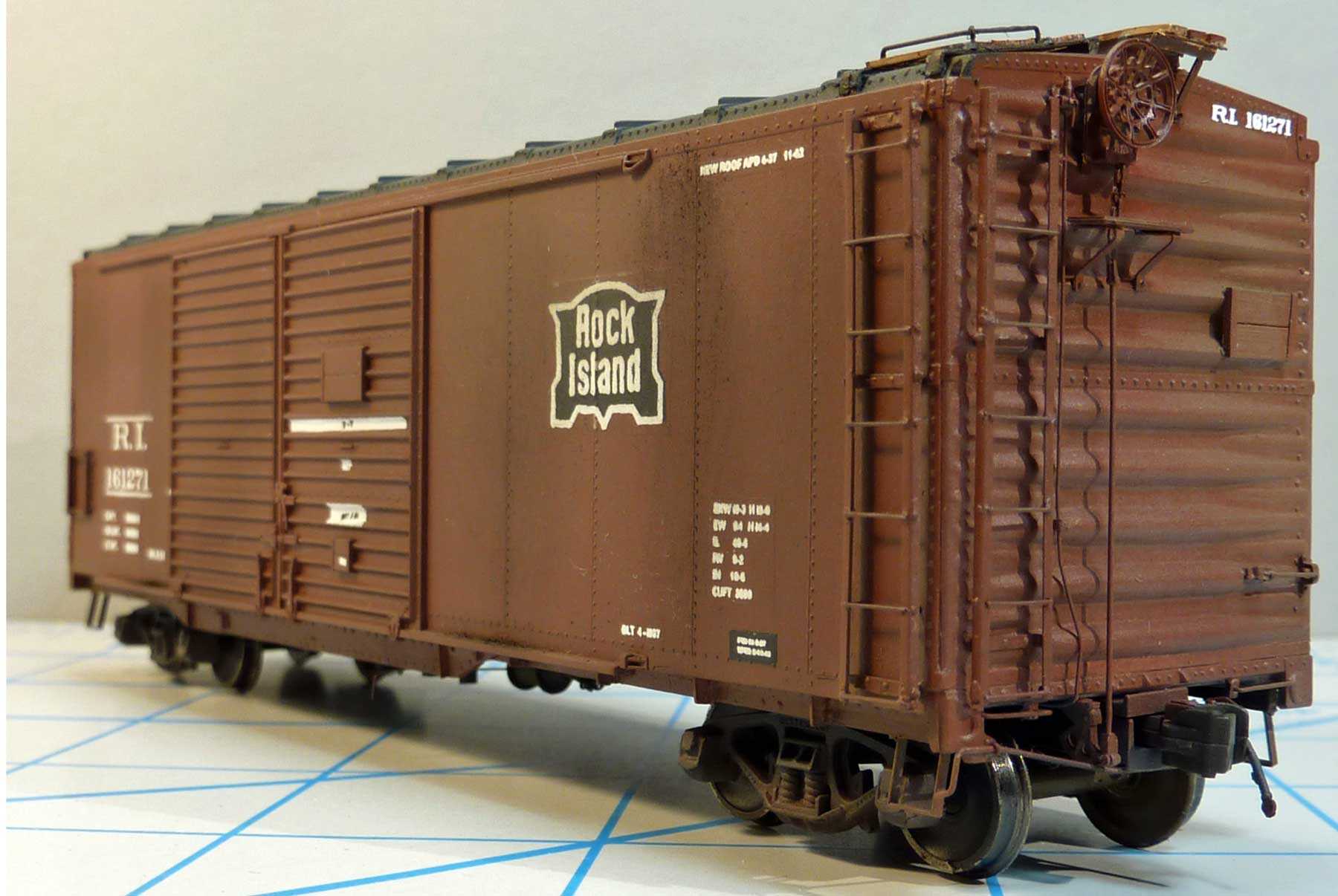
A JLC Micro Blade Saw was used to cut the end right above the rivets.
A 0.040-inch thick piece of styrene was glued to correct the height of the end using Tamiya styrene cement. Applying a liberal amount on the styrene creates a very tacky surface that sticks to the resin piece. After this dried, some Cyanoacrylate (CA) glue was applied from the rear.
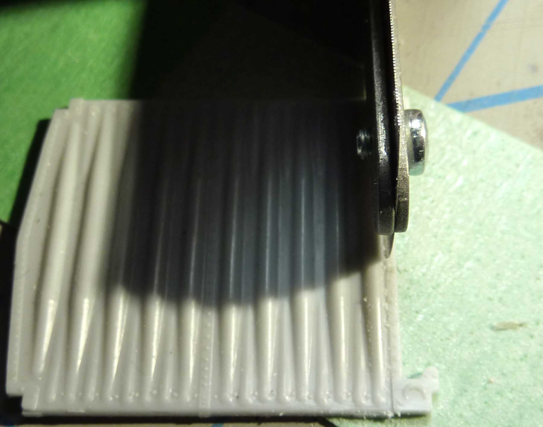
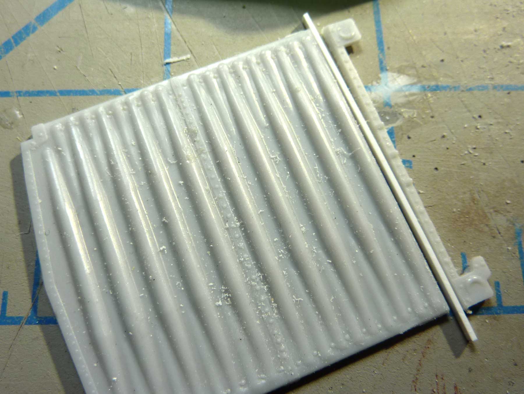
Here’s the completed car end with styrene spacer.
Underframe

The car underframe was next. Although the resin part was well done, it had a warp I could not remove. As I wanted more detail, a new underframe was scratchbuilt. 0.040-inch thick scribed Evergreen styrene was used for the floor. The center sill, floor stringers, cross ties and crossbearers were made from styrene using techniques described in the 2017 Shake-n-Take Erie double-door boxcar instructions. Those instructions also available through the 2018 Shake-n-Take on Groups.io. The reddish color bolsters were from a cutup Ribside kit in the scrapbox.
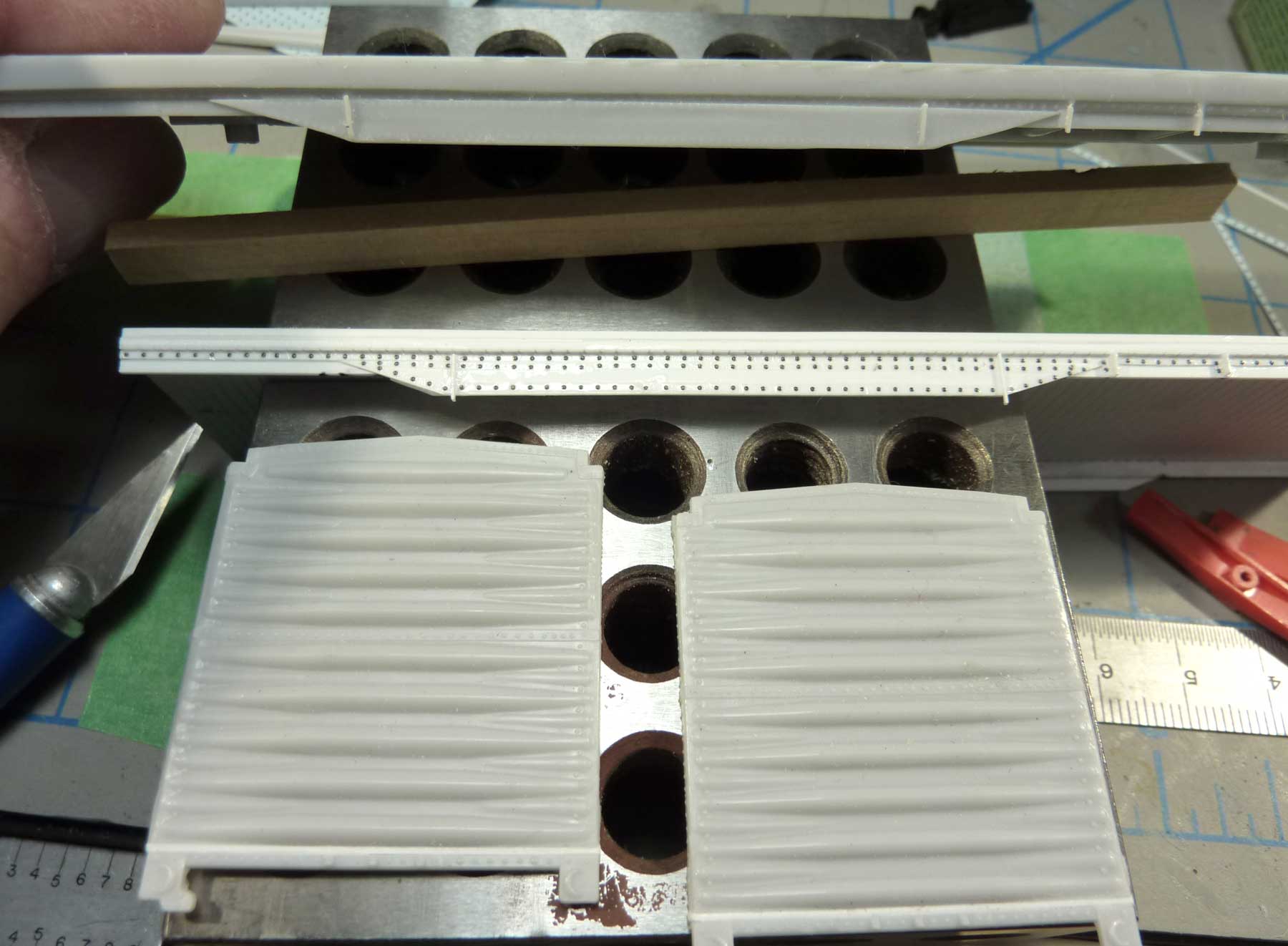
Above, you see the new scratch built frame with the resin part above. Both ends are ready for installation.

At this point, I could test fit the underframe to the MDC/Athearn car body.
Once I had the floor fit to the underframe, the resin ends were attached to the car. Liberal amounts of Tamiya Extra Thin glue were applied to the boxcar ends. The resin ends were set in place when the plastic car parts were tacky. As the glue does not setup right away, you have time to make fine adjustments. Once positioned, apply a bead of CA to the seam from the inside and add additional bracing for strength.
Brake system details
A number of fine details were installed on the underframe and on the end sills.
- Tichy Train Group AB brake components #3013
- Yarmouth Model Works brake levers YMW 403
- Tichy 0.008, 0.010, 0.0125, 0.015, and 0.019-inch diameter brass wire
- Moloco Trains air hoses RH-0307
- Precision Scale brake angle cock brackets # 39156
- Accurail Proto:HO scale couplers and boxes #1020
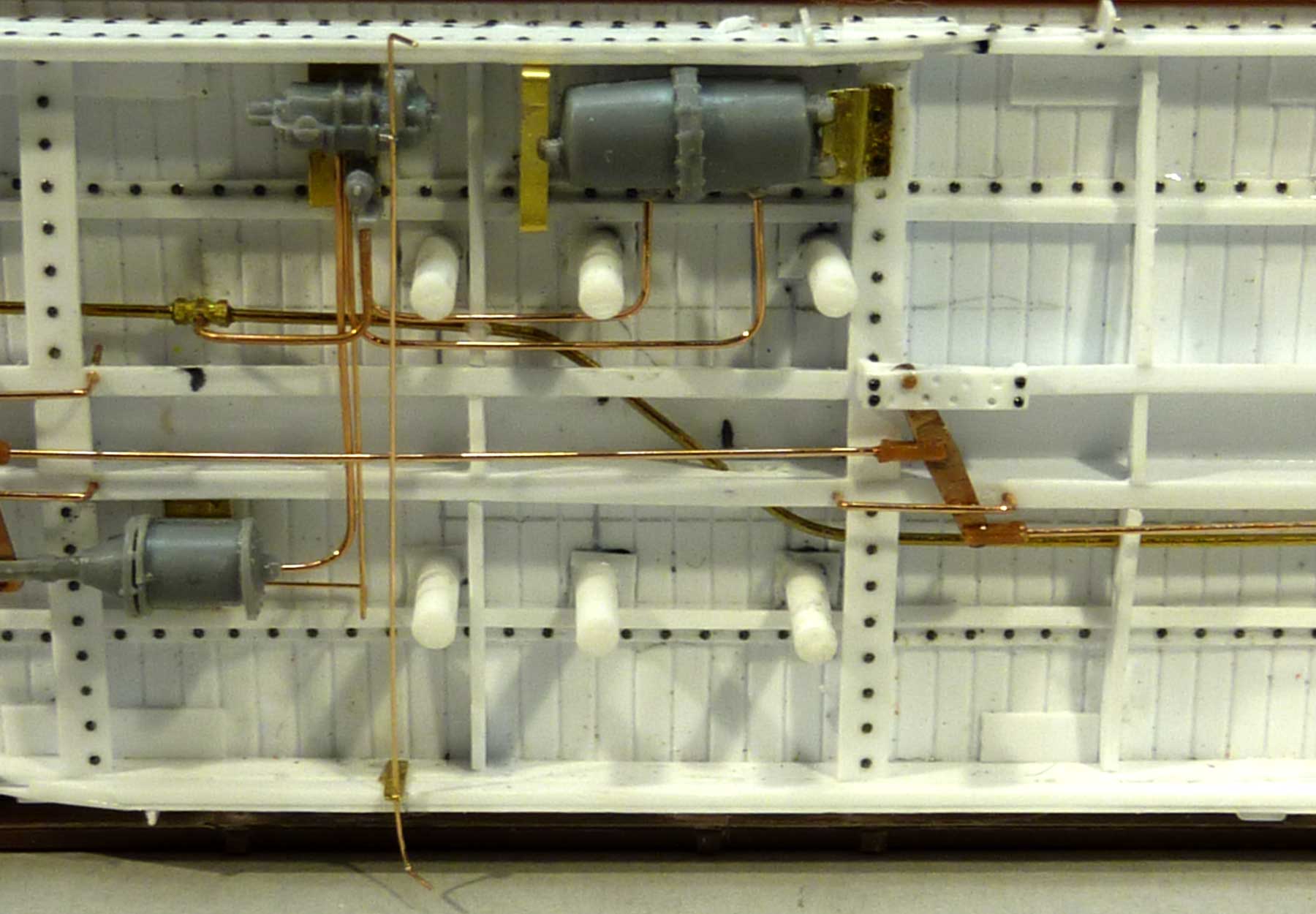
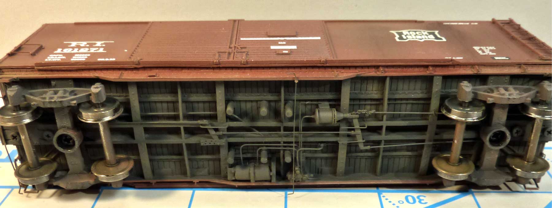
Chain storage tubes are a unique feature of early automobile boxcars. These extend down from the inside of the car into the underframe and are represented by styrene rods in the image above. The air brake piping must fit in around all these storage tubes. My model does not include all the tubes as some would interfere with the swing of the trucks.
The brake piping follows the General Arrangement Drawing. Gentle bends were made in the material per an article Gene Green shared on piping available in the RealSTMFC Groups.io file section. I also made a Universal slack adjuster from 0.005-inch styrene, per the General Arrangement Drawing.
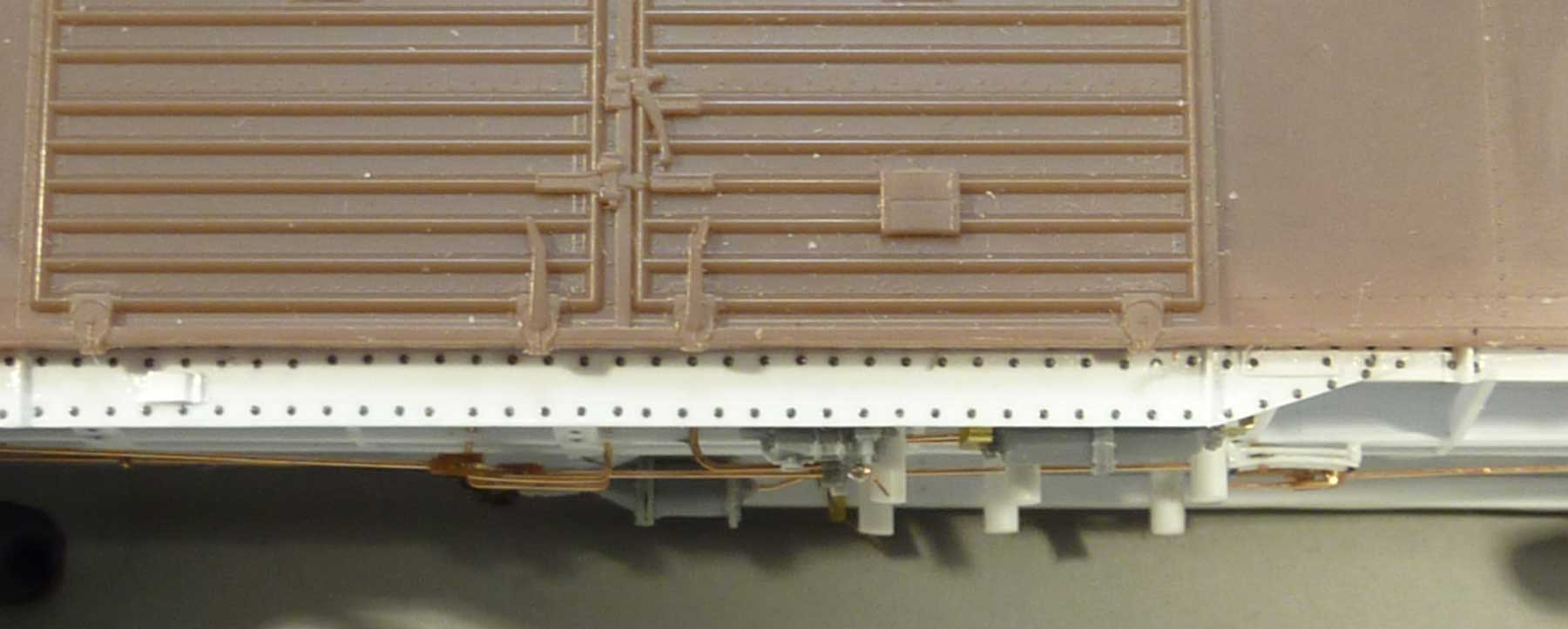
This side view shows the chain storage tubes and fishbelly door support. Note the defect card holder on left side and trust plate on right side of frame. MicroMark resin rivets (#84985) were used for underframe detail.
Car body details
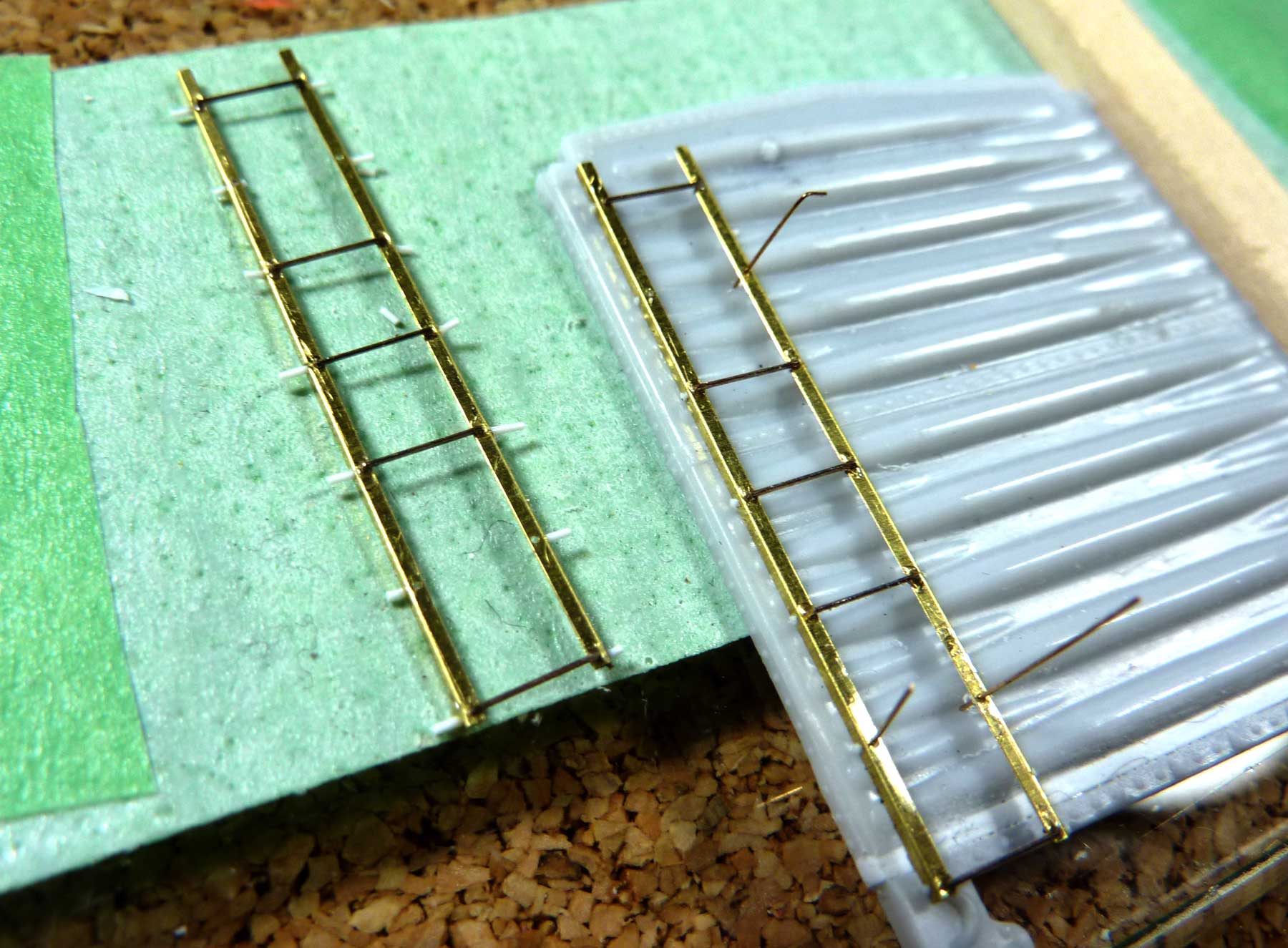
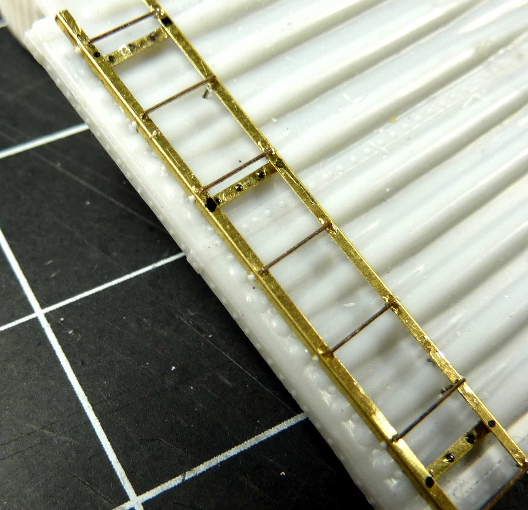
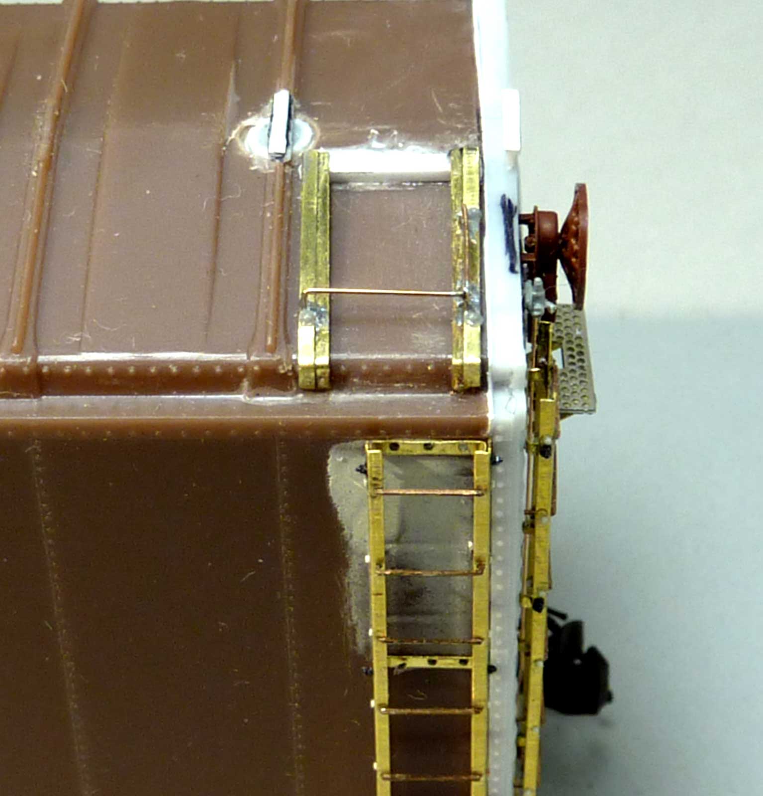
Yarmouth Model Works Ladders with 18-inch, 7-rung Stiles (YMW303) and Rungs (YMW353) were used to build unique Wine Style Ladders. Yarmouth 12-inch Straight Stirrups (YMW211) were also installed. On the left side of the image above, a ladder is being built.
Before bending the stiles, an additional 0.012-inch hole is drilled next to each rung hole in the side of the stile. After bending the stile and installing five of the seven rungs, CA is used to attach a 0.010-inch styrene rod in each hole along the side of the stiles. These represent nubs of the prototype ladder rungs that stick out. The ladder on the left shows untrimmed styrene and the one on the right you see has the styrene trimmed and four lengths of brass pins temporarily holding it in place where the four locating holes are drilled. Two of the rungs will use longer legs to pin the ladder assembly to the car.
Here’s the finished ladder. Three mounting brackets were formed from 0.006-inch brass with resin rivets and installed. Not seen in this photo are the Grandt Line square nuts and bolts added next to each mounting bracket. Each ladder has 35 parts.
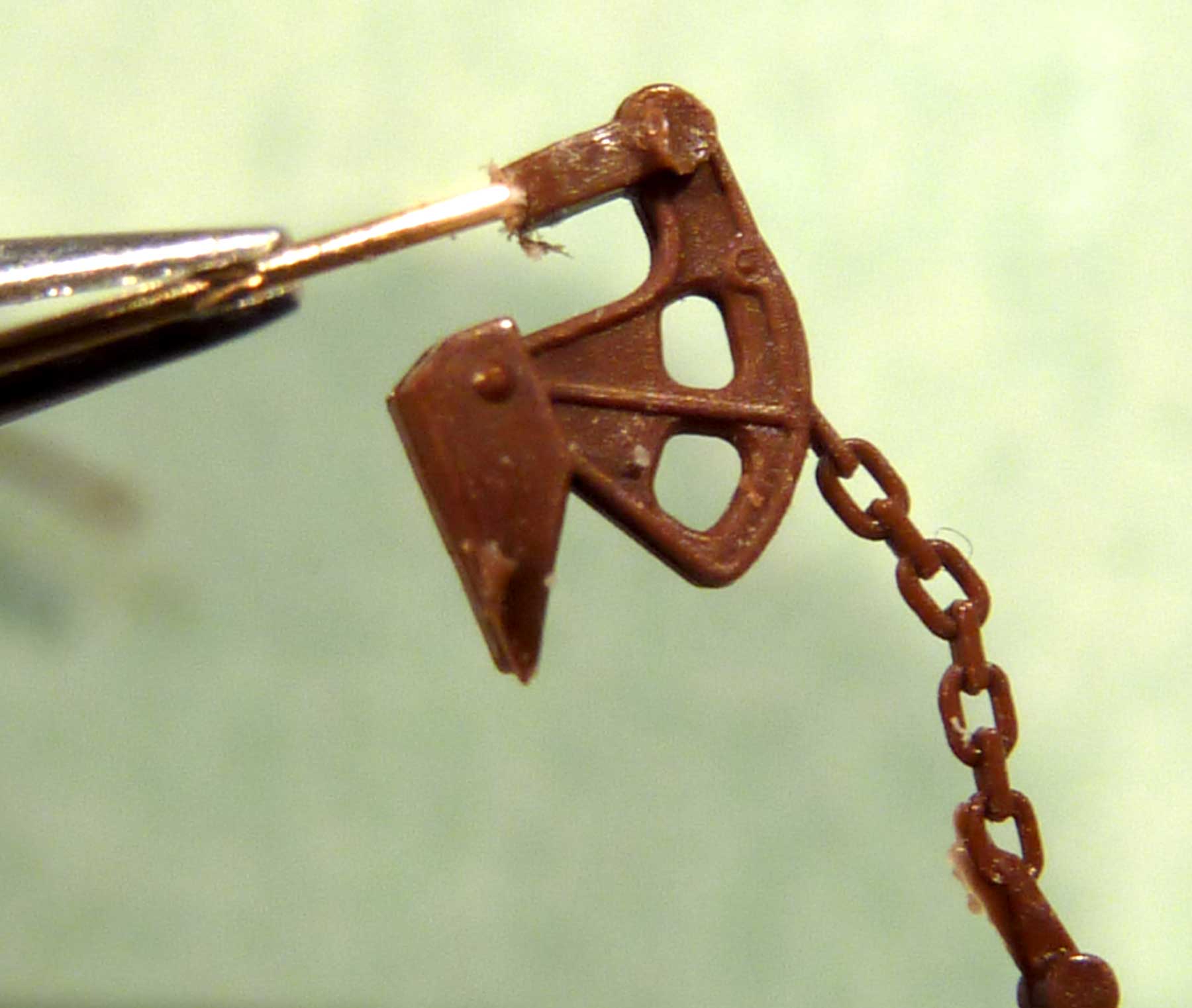
The B-end details are standard, however I used a different method to attach a Kadee Ajax brake housing (call Sam at Kadee to purchase these direct). The Kadee brake rod length was too short so the brake rod was cut off. I wanted to use the Kadee chain and bell crank, so I drilled a new hole using a 0.009-inch drill bit and enlarged it to 0.011-inches to fit 0.010-inch mounting wire. The wire was not true to the size on the package. I used Guhring drill bits from Germany for this task.
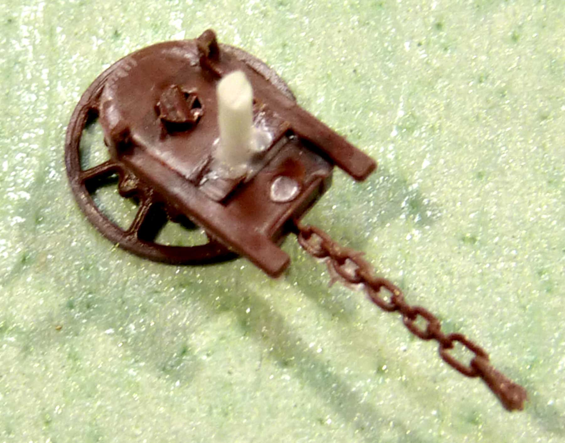
Mounting Kadee brake housings can be a challenge. My method is to drill the backside and insert a 0.040-inch styrene rod. After applying styrene cement, allow it to dry. Drill a hole in the car end then insert the assembly and use styrene or CA to attach.
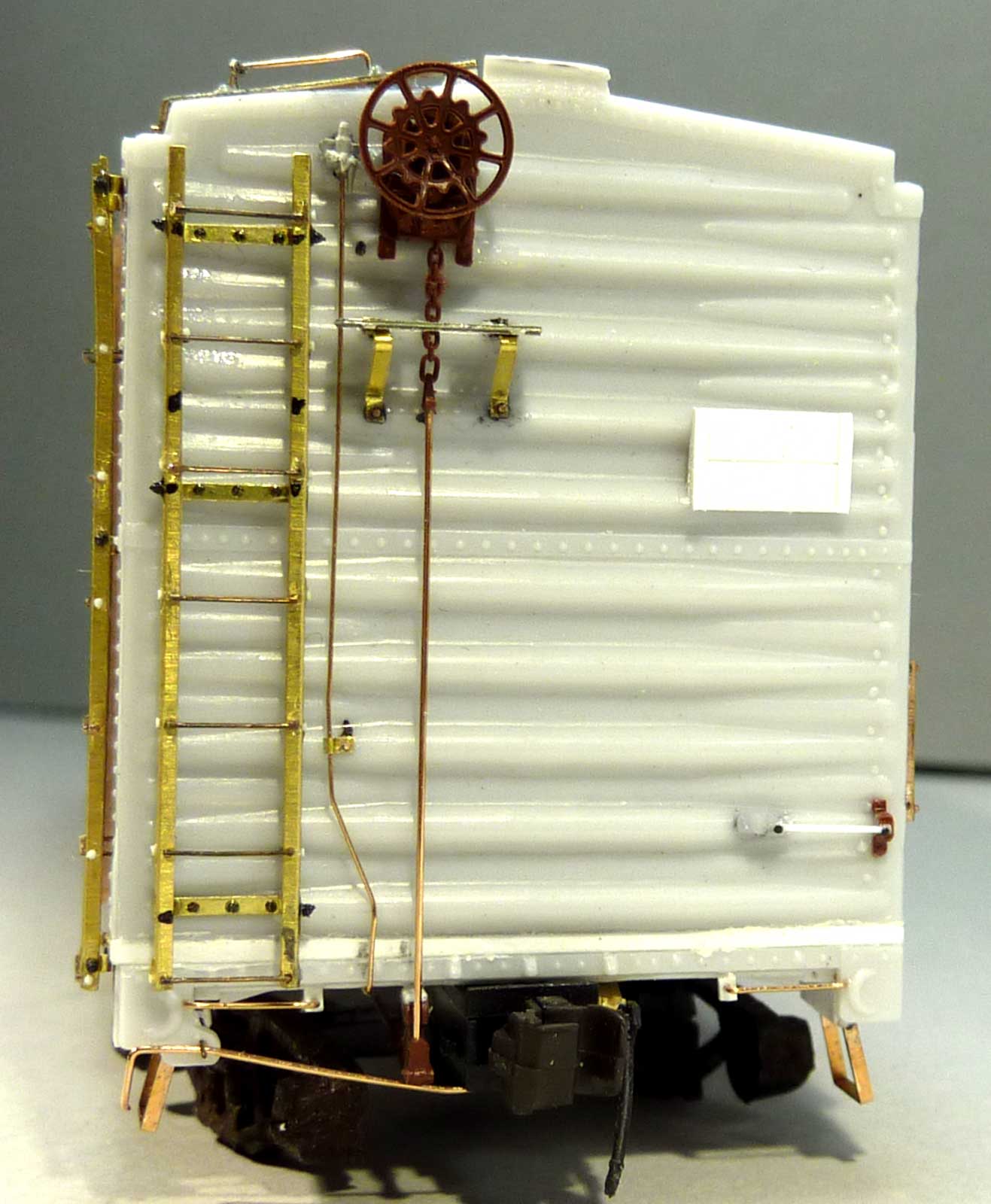
Here’s a look at the B-end of the model. The Kadee brake housing and bell crank have been mounted. A length of 0.010-inch brass wire replaced the plastic piece that was too short. A Plano Morton brake step (#11322) is mounted on brass pinned supports cut from 0.006-inch sheet brass. The Grandt Line nut and bolt detail on the ladders is more obvious here. A Precision retainer valve # 31796 was also installed.
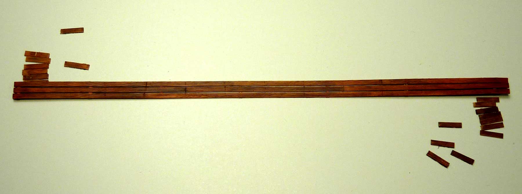
The running boards on this car were wood with metal supports for the short laterals. I have not tried to model these before. Two lengths of 0.006-inch brass of different lengths were soldered together, cut, and bent to shape. L-shaped grab irons where bent and soldered in place. Boards will be 0.015-inch thick styrene leaving about 0.009-inches of the boards ends exposed.
The running boards are made from 0.015 x 0.060-inch styrene and were painted and pre-weathered before installing. The roof is black and I wanted the running boards a red shade similar to the sides and ends. I scribed the wood grain and nail holes then painted a base coat of Depot Buff. After this was dry, a thin wash of black was applied. Next, Pan Pastels in various shades of oxide reds and earth tones were applied. The parts were lightly oversprayed with a coat of the car body color.
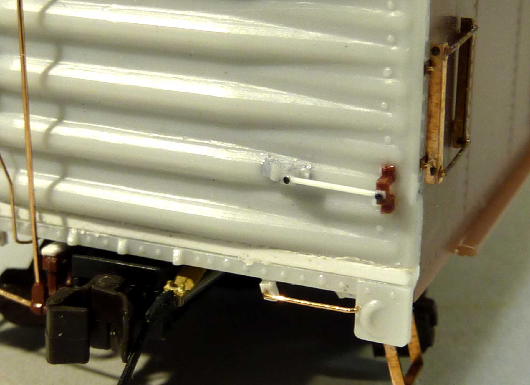
Here’s an end view showing an improvised grab on right side of the car end. This was made from two styles of grab iron brackets found in the scrap box (IM and Branchline). A piece of 0.010-inch styrene rod was used for the grab. The ends were flattened and rivets harvested from an Athearn boxcar body were installed. Also seen on side of car is the Yarmouth two rung ladder YMW305 and modified with rung/rivet detail.
Finishing Touches
The car body was primed using Badger’s Stynylrez Gray Primer SNR-402. The sides and ends were sprayed a custom mix of Modelers Decals and Paint to make a Carhide Red color as mentioned by Ed Hawkins in the Shake-n-Take instructions. Six parts Boxcar Red were mixed with two parts Caboose Red. Vallejo Black Gray (#70.862) was used to represent the cement black roof. I also used this for the underframe.

The sides were sprayed with a coat of Pledge/Future before the Steve Hile custom decals were applied. I used set #25. Various chalkmark decals from Speedwitch and Sunshine were applied to the sides.
Car was over sprayed with Model Master Satin Finish and a small amount of Pan Pastels applied. At this point I wanted only light weathering.
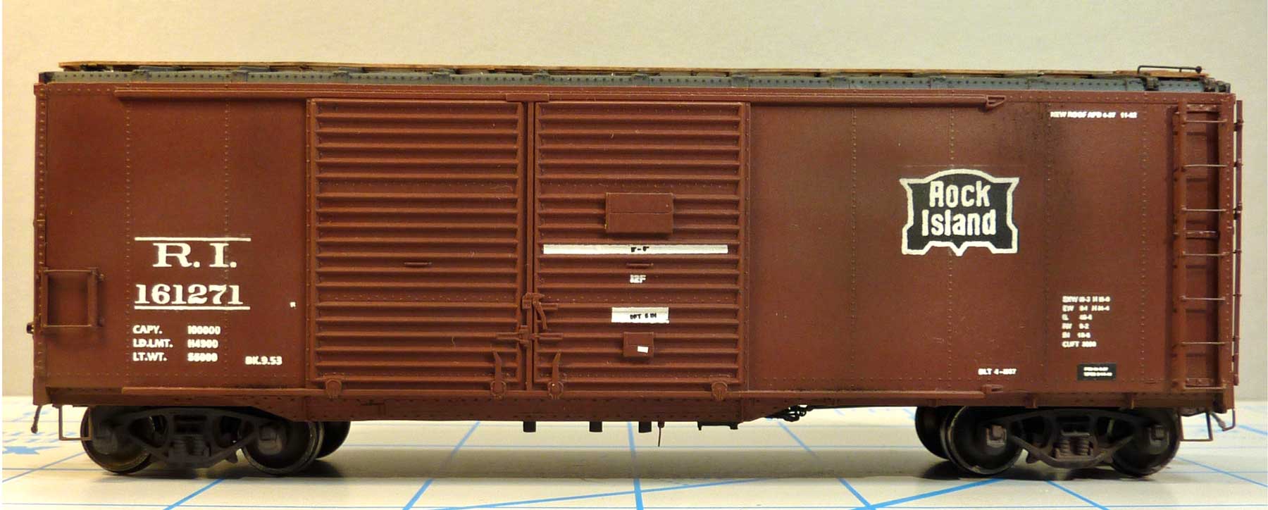
Overall this was a fun project. I learned new techniques building off a General Arrangement Drawing. I am thankful for the Shake-n-Take folks, Schyller Larrabee and Greg Martin, and others that made this project possible.
George Toman
We thank George for sharing his work on this interesting Rock Island automobile boxcar. He is building quite a fleet.
Questions and comments can be posted below. Please follow the instructions so your comment can be posted. All comments are reviewed and approved before they appear. To subscribe to this blog, enter your info for a comment and check the last box to notify of new posts by email. Share the blog link with other model railroaders.
I’ve learned some new techniques, amazing detail, very convincing model, well done.
I’m Not worthy, excellent model!
Beautiful job, George, so much better than mine! You have uncovered some sources and details that make for a superior model.
George,
There’s much to learn from the techniques you post here. Thank you for sharing.
Jim Kubanick
Morgantown WV
Another A+++ build George.
Outstanding work, especially on the details like the ladders and brake gear. Well done!
Magnificent!!!