Here’s part two from Jerry Hamsmith and his group building this recent Resin Car Works kit.
The AB brake system for this car is if nothing else, interesting. The drawings for the New York Central gondola, provided by the NYCHS, show a number of additions to the normal brake rod arrangement. The original drop doors required them to not be the normal straight line connections. Additionally, the reservoir and the control valve are next to each other on the same side of the car. This was likely due to the most convenient arrangement when converting from the original K brake system.
When Frank Hodina was putting together the master kit, these prototype drawings were not available and the extra piping was not included. Because of the drawings, an option to model an updated brake system was available. Two of the group decided to try it whereas the other two went with the simplified version.
Simplified Version
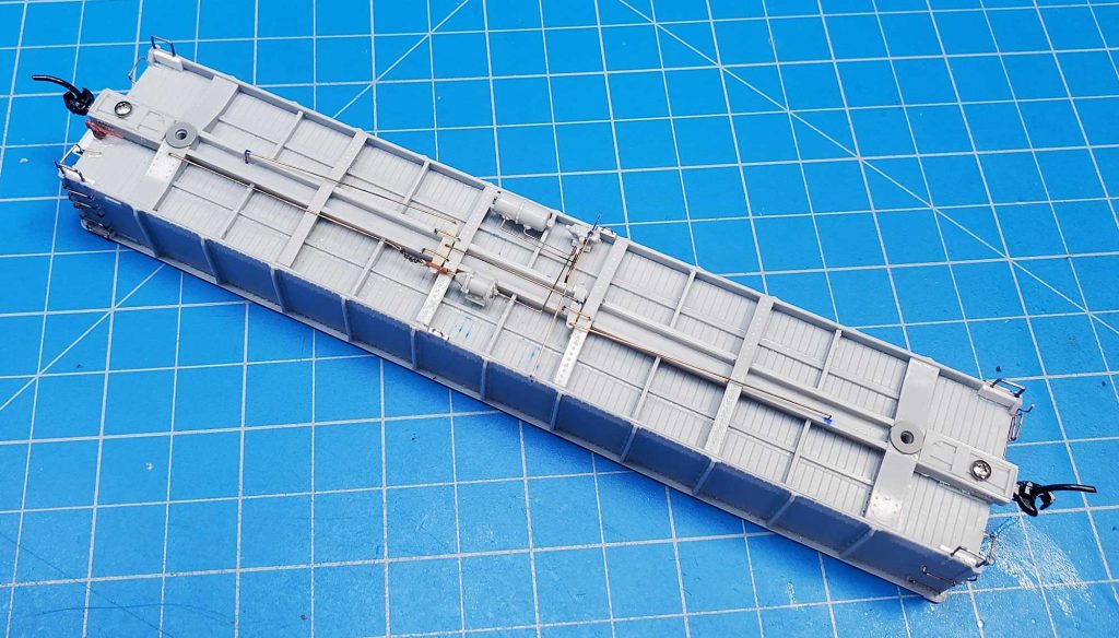
The simplified version essentially required copying details from the lead image, which was provided in the instructions. The addition of a train line would be the first step, although only one member of the group chose to install this detail.
Using a #70 bit, holes were drilled through each crossbearer at the car floor and a 0.020-inch diameter brass wire line was added. The line is actually three pieces: the rightmost piece in the picture is the small section below the center sill, the middle section of the line runs from the top of the sill to a Tee-connection (a small piece of styrene tube) in the middle of the car, and the third section continues from the Tee to the left bolster. As oriented for the picture, the B end of the car is to the left. The dots on the floor of the car indicate the locations of the reservoir, cylinder, and control valve. The Tee will serve as the connection for the dirt collector.
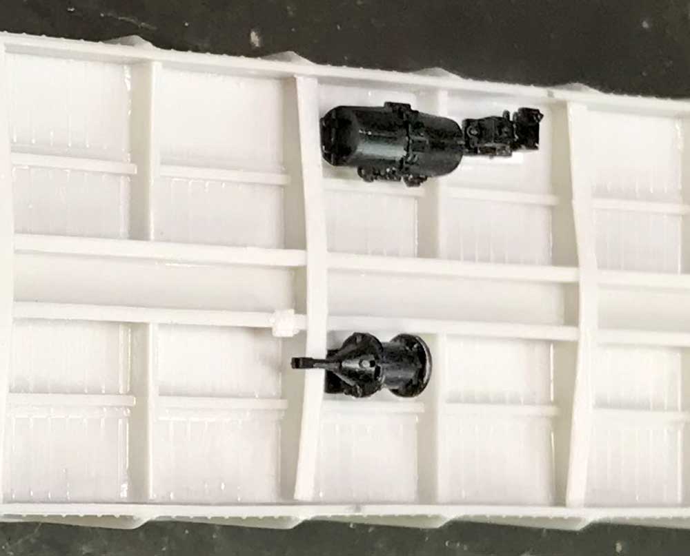
For the rest of the group, adding the major brake components was the first step and they were spotted following the instruction photos with the reservoir and the control valve positioned next to each other. I used Cal-Scale parts. The reservoir and the control valve mounts were made from scrap styrene. The goal was to get the height of the reservoir connection points (holes) at bottom of the center sill level and the same level as the control valve connection points.
The Cal-Scale AB set has a part that serves as the cylinder mount, which I used. The dirt collector, a Tichy part included in the kit, could also be attached to the brake line and to the control valve. Some in the group did so, but others opted not to.
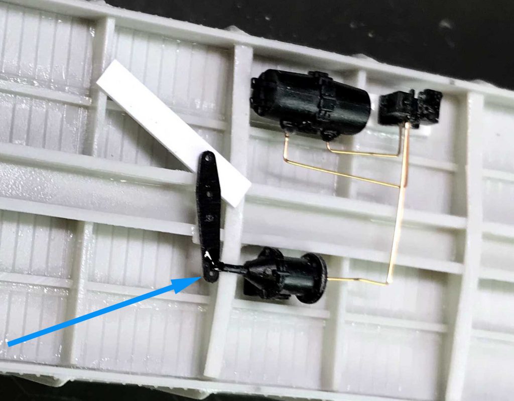
Next, the brake piping from the reservoir to the control valve and from the cylinder to the control valve was installed using 0.010-inch diameter brass wire. Once the piping was completed, I added Cal-Scale brake levers. To attach the brake lever to the cylinder piston, a scrap piece of styrene was used to hold the lever in place while the glue set. Before attaching the lever to the brake piston, I drilled an additional hole in the lever for the eventual attachment of the chain. The blue arrow in the above image points out the hole.
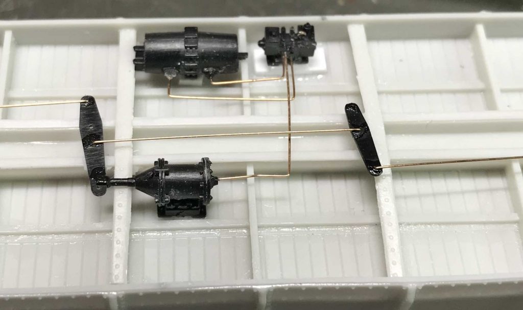
A small scrap piece of styrene was used to create the fulcrum on the center sill for the A end brake lever to sit on. I attached the 0.010-inch diameter phosphor-bronze brake rods directly to the levers.
Others used clevises made from Tichy turnbuckles for the brake rod connections, as seen in this image.
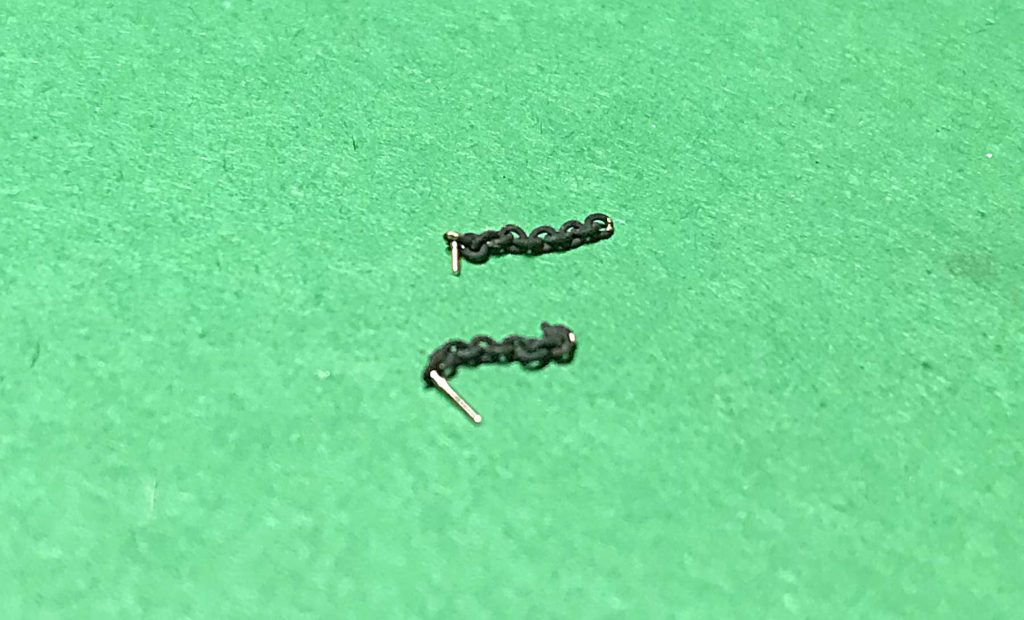
Adding the brake chain was the next step. The chain is 42 links per inch from Campbell Products and the wire is 0.010-inch diameter phosphor-bronze from Tichy. I cut about 12 links from the original length of the chain and inserted a short scrap piece of the wire into one end link. The piece was glued with a short length left to insert into the brake lever. The excess was clipped off after the chain was attached to the lever.
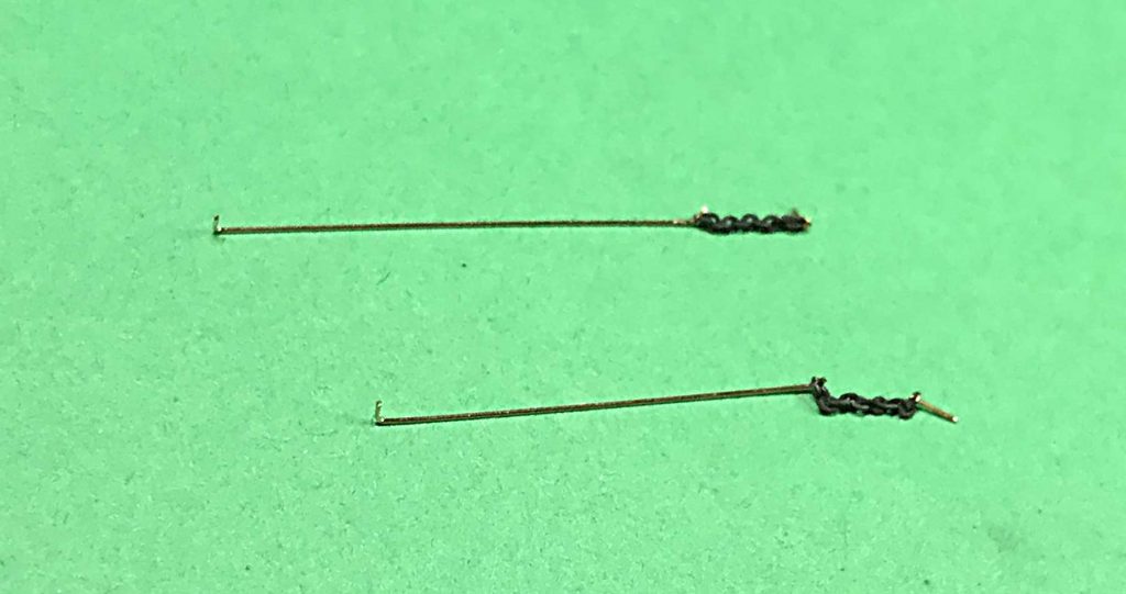
A 1½ inch length of wire is used as the connection to the hand brake wheel. It extends to at least the minor cross tie before the bolster on the B end of the car. A small hook was created on the end, inserted into the last link on the other end of the chain, and glued in place.
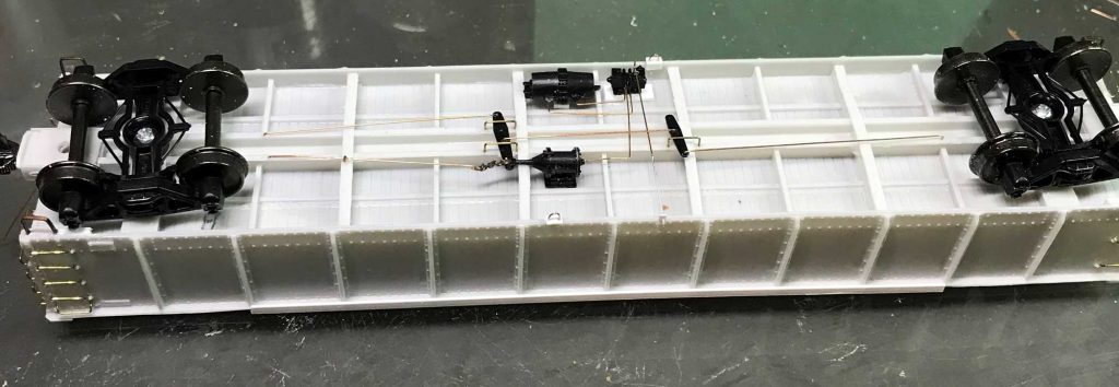
Here’s the hand brake rod and chain installed in the model. The other end of this brake rod is bent to insert into a hole on the center sill where it is glued into place.
Once the brake rods were installed, I added the brake lever hangers from the kit-supplied 18-inch grab irons. The tow loops and the pressure release rod were not added until later in the build.
That wraps up the simplified brake system installation. The next part will review the updated systems that we found in the NYCHS documents.
Thanks to Jerry Hamsmith for part two of this group gondola kit build. Another part will be posted soon.
Questions and comments can be posted below. Please follow the instructions so your comment can be posted. All comments are reviewed and approved before they appear. To subscribe to this blog, add your email address to the function at the bottom of the right column on the main page. Share the blog link with other model railroaders.
