George Toman returns with details on his latest HO scale resin freight car kit. Here’s George with the story.
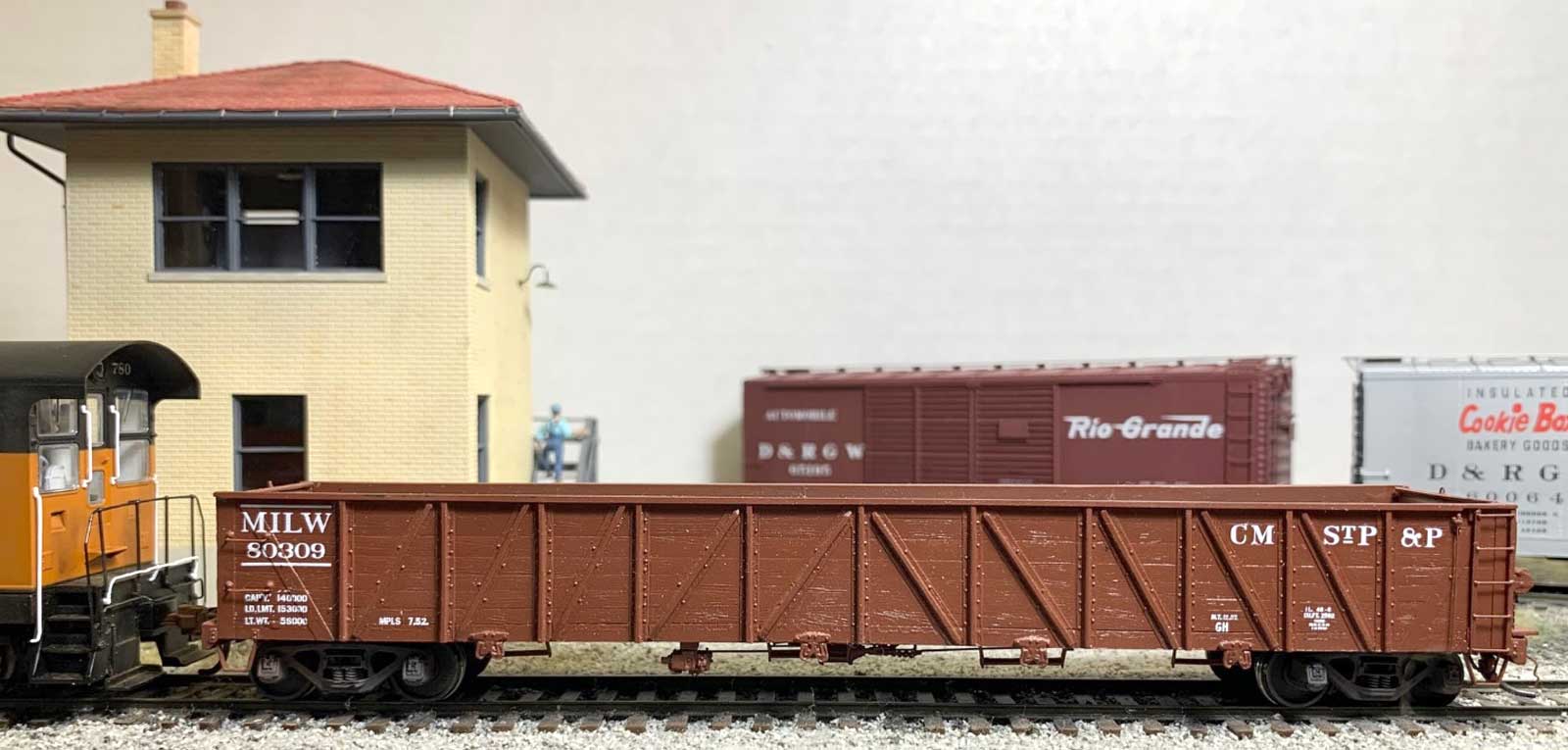
Being a Milwaukee Road modeler, when Frank Hodina of Resin Car Works finally produced a Milwaukee Road 48-foot, 6-inch composite gondola (RCW Kit 15.0), I knew I had to have one. So, I bought two.
This is a beautiful resin kit with most of the work already done for the modeler, making a quick and easy-to-build kit. Of course, that didn’t stop me from making this into a longer project by adding some extra details.

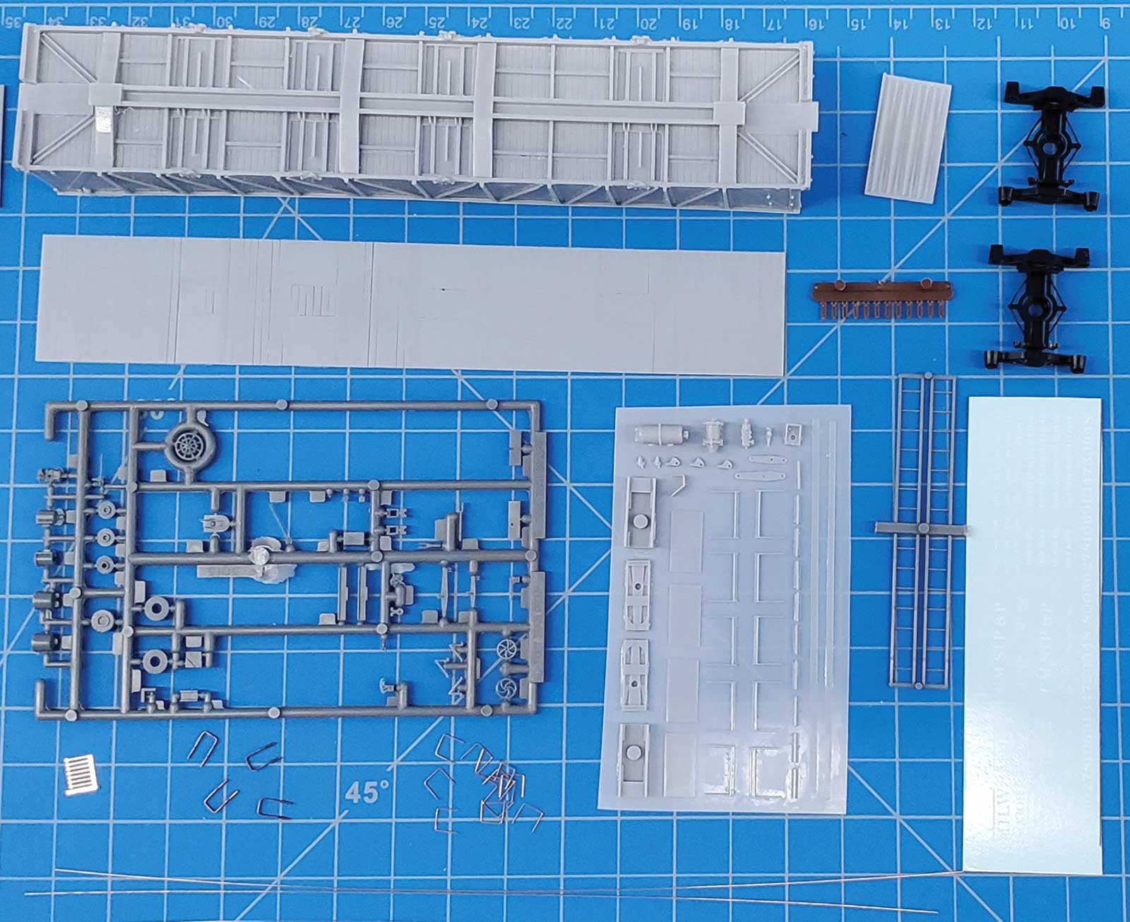
I downloaded the instructions from the Kit 15.0 extras page on the RCW website and checked the kit contents. I generally follow the kit instructions, but and made changes to add the following details.
Before I start most projects, I search for additional support material such as available photos and general arrangement drawings. I was lucky and found a drawing of the gondola on page 245 of the 1946 Car Builders’ Cyclopedia. The drawing helped me to understand the layout of the Klasing ratchet hand brake and end details.
Another feature that I noticed were the side ladders. If you look closely the stiles appear to face outward. I have seen this practice on other Milwaukee cars and thought it would be a nice detail to include on this car. After reviewing photos and drawings, I decided to add a train line, additional details for the Klasing hand brake, wire loops on drop ends, photo etched ladders, and a bleed rod.
My first step was to wash all the resin parts with Dawn dish detergent. I decided to add the train line before any assembly as most the work on the underframe was complete.
I searched prototype photos or drawings for the brake arrangement but had no luck. I did a search for similar built cars and found a couple of photos showing the train line running along the center sill as to not interfere with the drop door hardware and hinges.

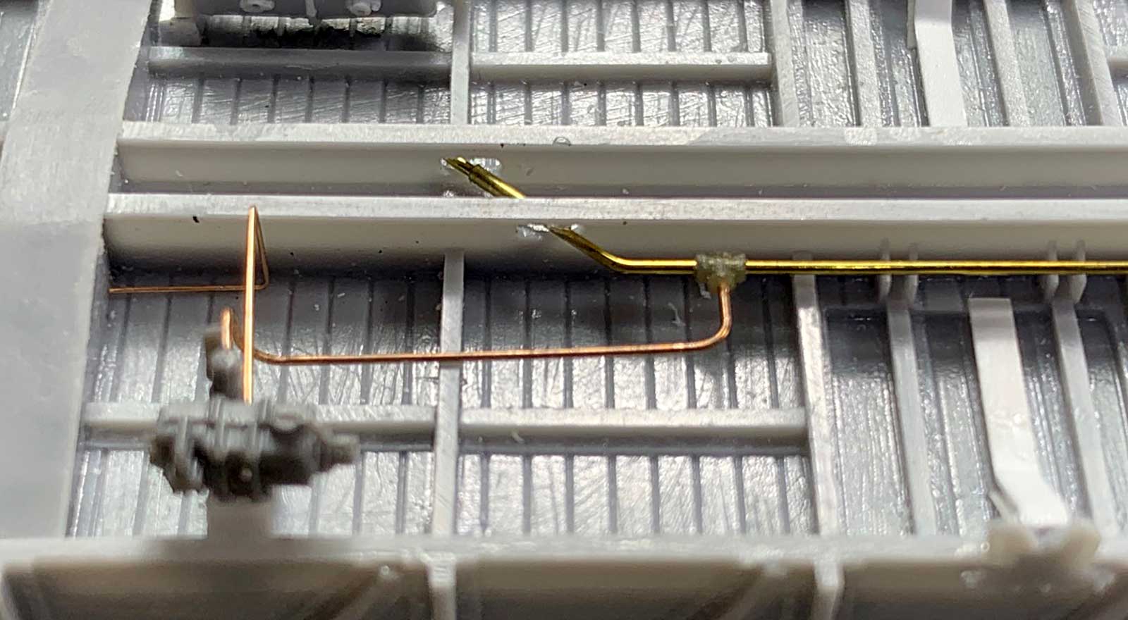
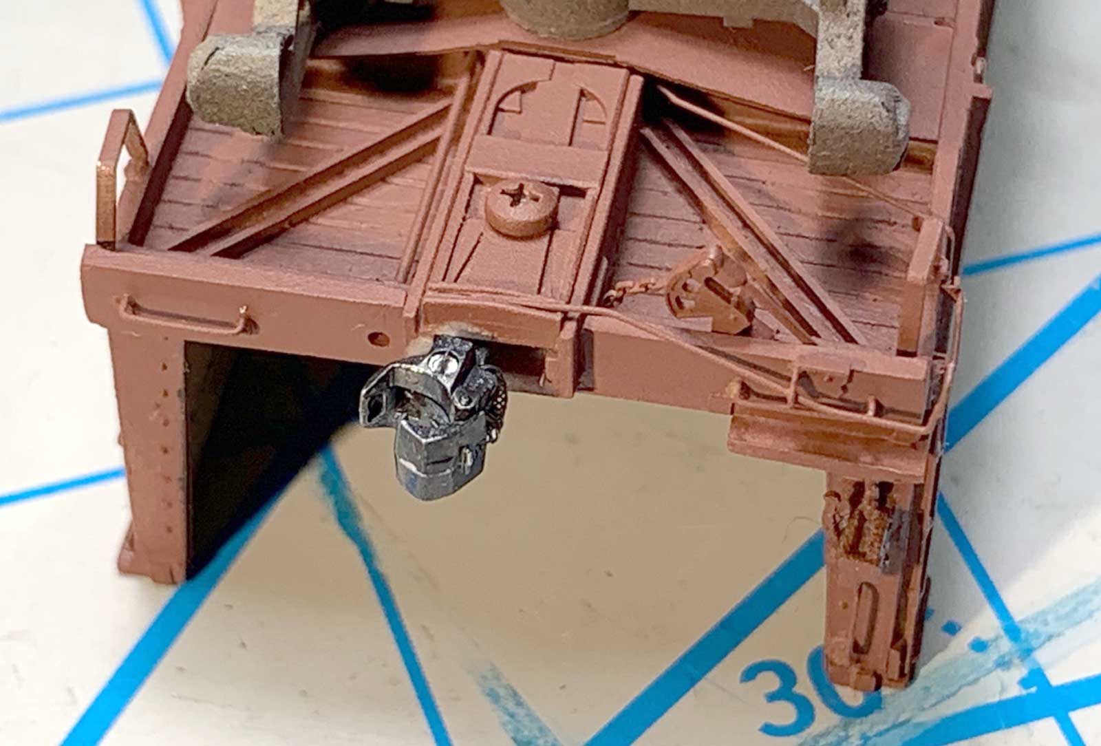
The image above shows the locations of oval openings in the center sill and 0.030-inch holes in the bolster and cross bearers. I drilled out a 0.030-inch hole in the end sill, then used a piece of 0.030-inch diameter piano wire chucked into a Dremel motor tool to drill the bolsters and cross bearers. The longer piano wire was a better option than a short drill bit.
After I installed the 0.019-inch diameter wire train line, I added the three-way valve and 0.015-inch diameter wire air connection to the 3D printed Tee, and the 0.008-inch diameter wire line that goes to the retainer valve.
Pay attention to the orientation of the car and mark the B end clearly. The B end is easily identified by the retainer valve cast in place on the car side.
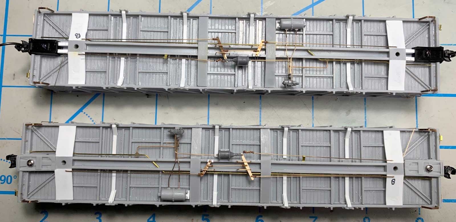
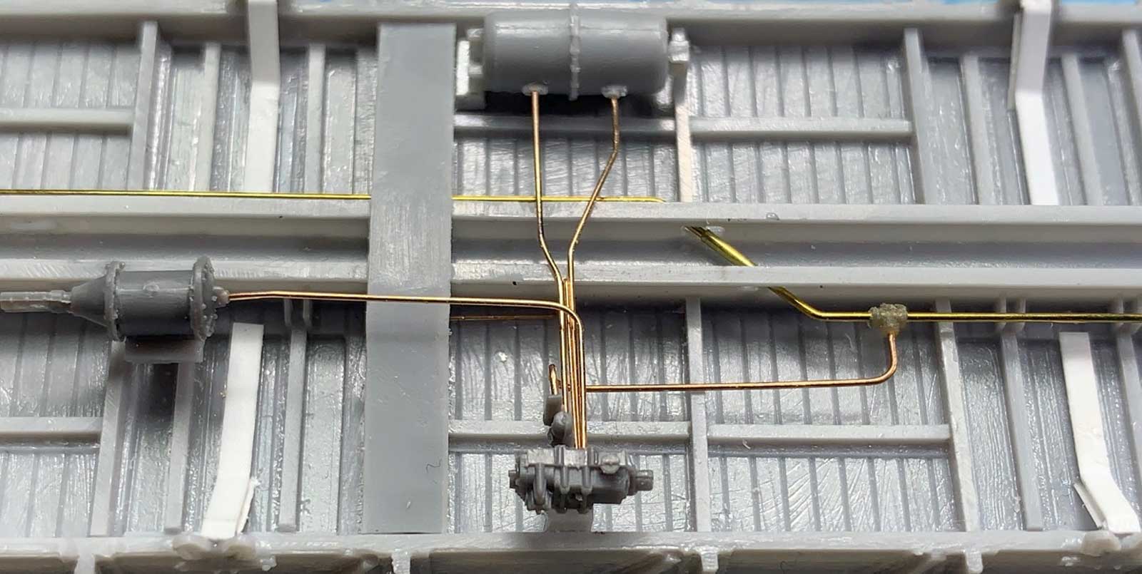
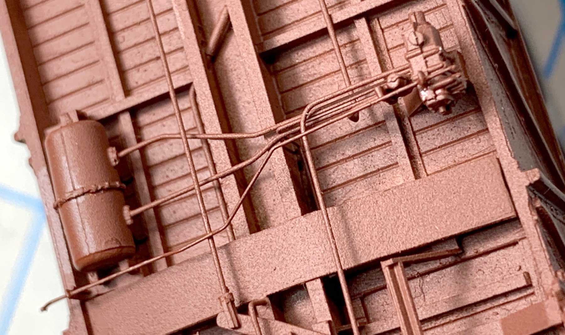
Seen above are the two car underframes with all brake parts in place. I clearly marked the B ends on the bolsters. An extra detail is the 0.008-inch diameter wire mounted on an angle that runs from the retainer valve on the car side to the bolster.
I was inspired to install the angled retainer line after reviewing a photo available on the Kit 15.0 extras page.
I installed two different draft gear boxes on these models. One is the resin RCW draft gear included in the kit. The other is using Kadee scale draft gear boxes as it will be shipped to Lester Breuer for service on his Minneapolis & Northland.
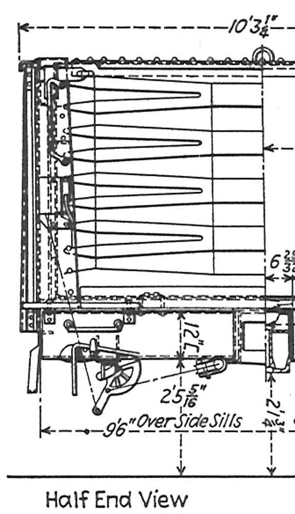
The next detail to add was the Klasing ratchet brake housing. Using the photos in the kit extras page and the above blowup of the end drawing, I came up with a method to model this feature.
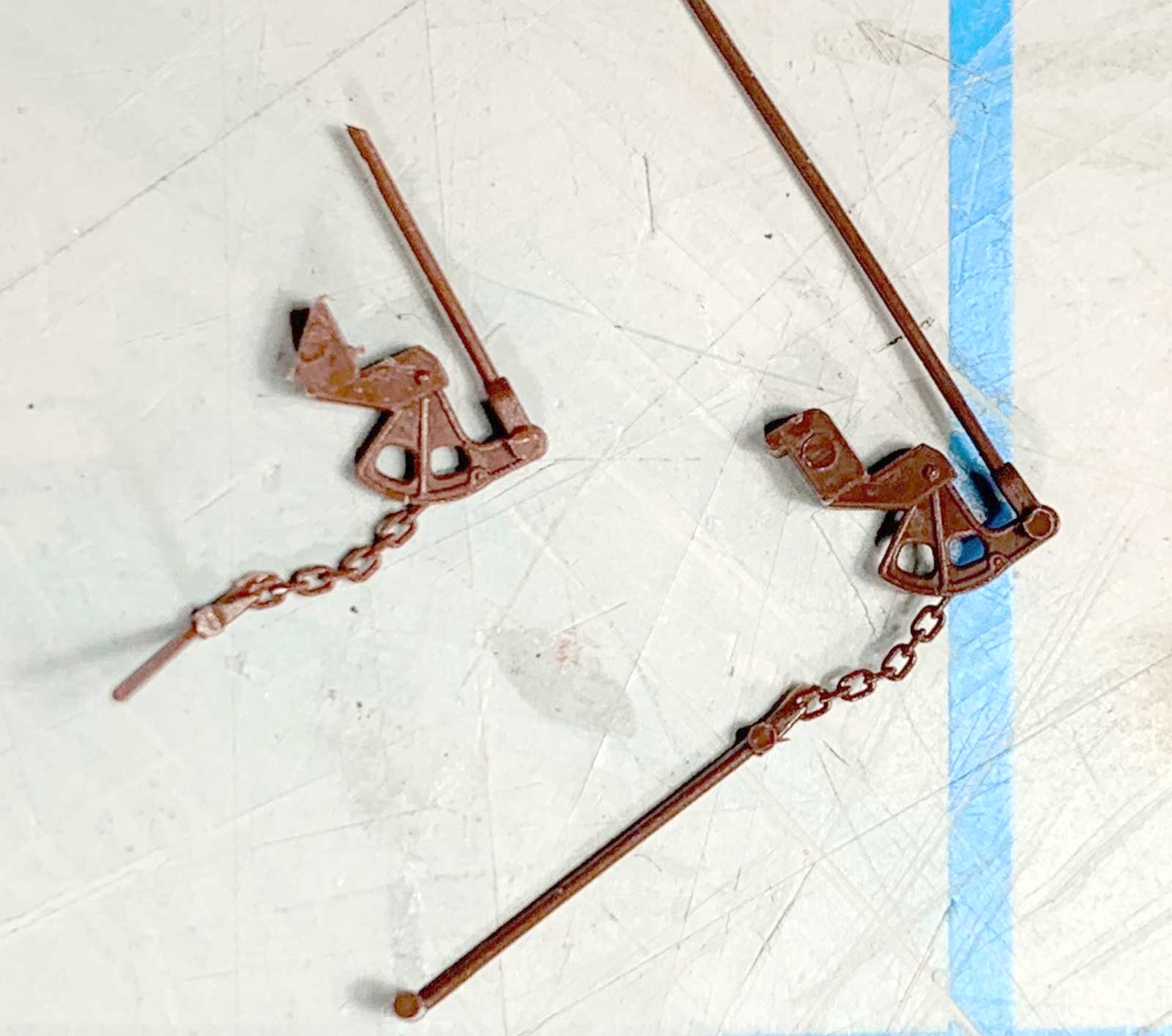
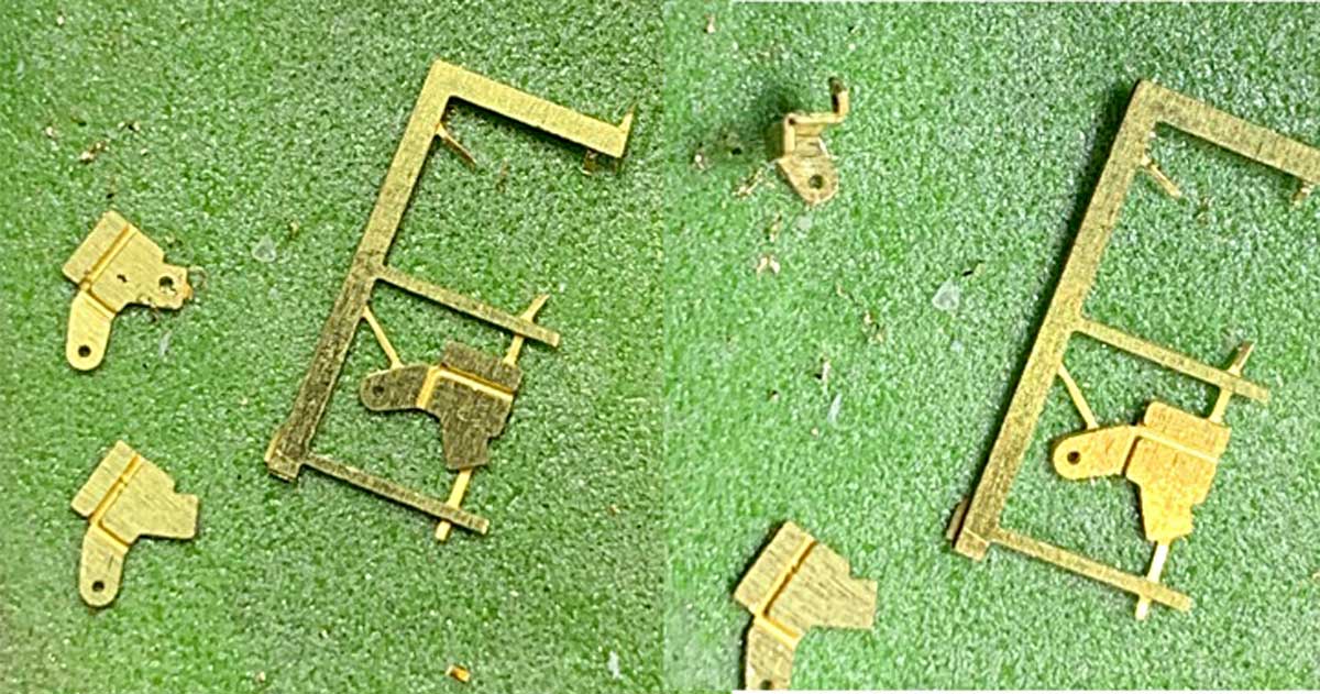
After looking through my odds and ends, I decided to modify a Kadee fulcrum to make a close copy of the prototype. Note in the above image that the top left fulcrum has a part of the base sliced off on roughly a 45-degree angle. This was a trial and error to come up with this angle.
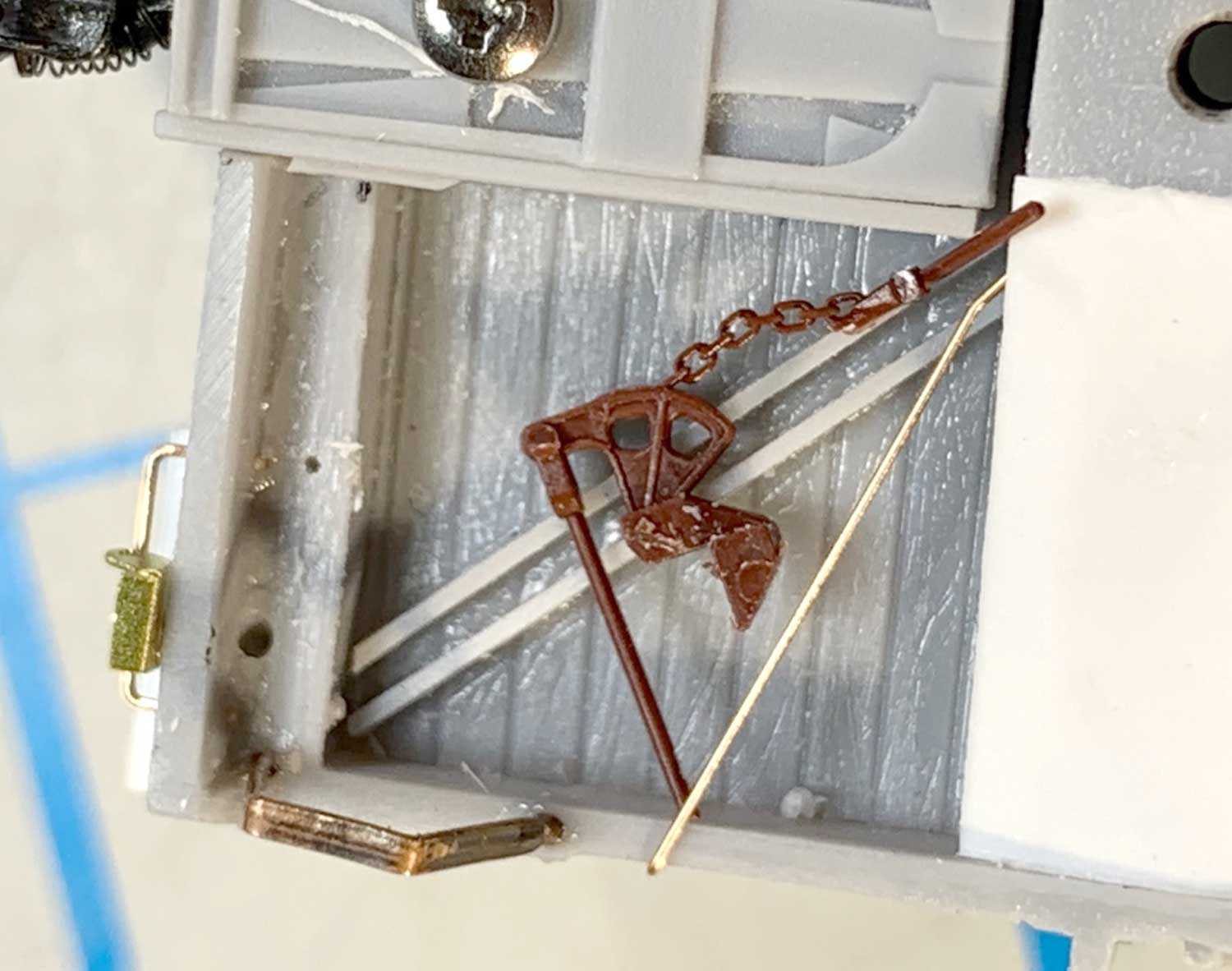
In the above image, one of the Kadee parts is cut and ready to be installed. A large hole near the corner was drilled at an angle toward the direction of the Klasing ratchet brake housing and chain. I also drilled a #80 hole in the bottom of the end sill in line with the end grab. A piece of 0.012-inch diameter wire will be inserted to fit into a #80 hole in the bottom of the Kadee fulcrum at the 45-degree cut. The wire will help keep it secured to the model.
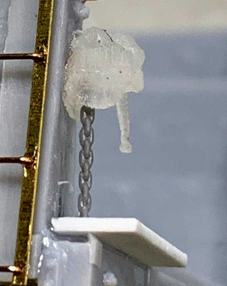
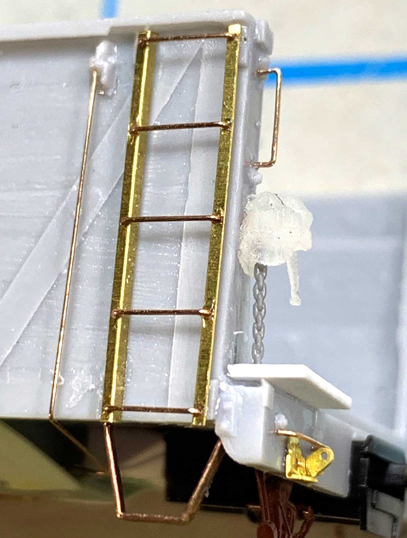
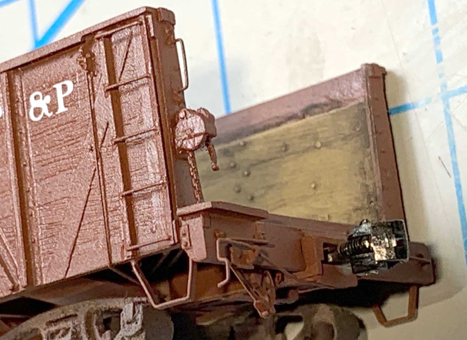
The Klasing ratchet brake was mounted per kit instructions to the B end of the car. I did this by drilling a hole to fit the mounting pin on the back of the 3D printed part. I added a length of chain from the Tichy AB brake parts included in the kit. A piece of styrene was installed as the brake platform.
To the right of the Kadee coupler, I marked the location for the train line. I drilled a 0.030-inch diameter hole and followed up with the long 0.030-inch diameter piano wire to drill the bolsters and cross bearers.
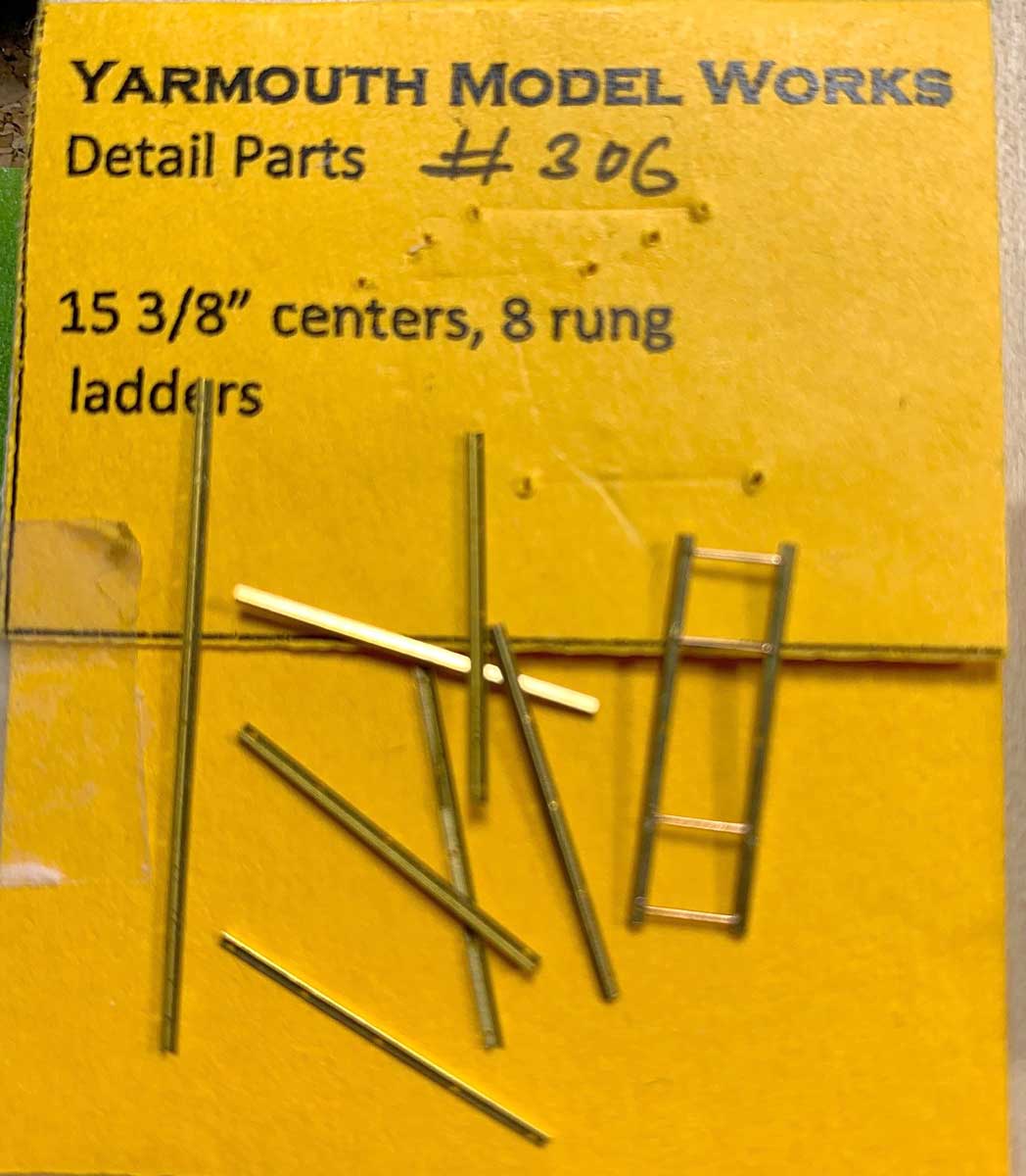
For the ladders. I decided not to use the kit parts. I found the Yarmouth Model Works #306 ladders were almost spot-on for the prototype with a 15-3/8-inch rung spacing. I also wanted to have the stiles with the L facing outward. I cut the stiles down to a five-rung height then calculated the mounting lug spacing cast onto the car sides for the Tichy ladders. This just happened to be 17-inches, as per the drawings.
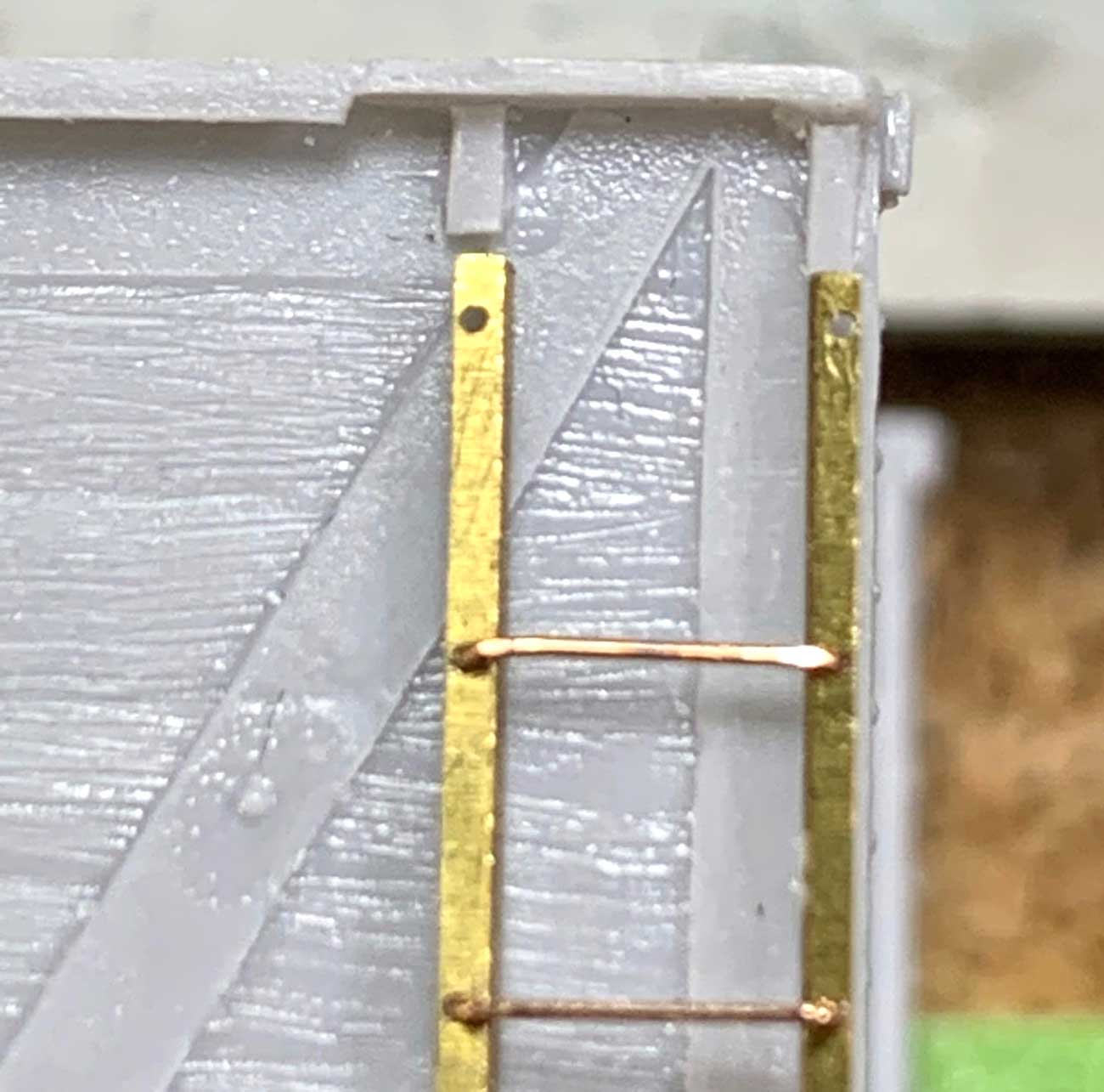
I test fit the ladder assembled with top and bottom rungs left off. I checked the distance between mounting tabs and stiles. The mounting tabs needed a slight trim and cleaned for a better fit.
Next up were the cut levers. I modified Yarmouth etched metal parts. In the above photo, I drilled #80 holes in the parts before bending. It’s best to drill holes in etched metal parts before bending them into shape.
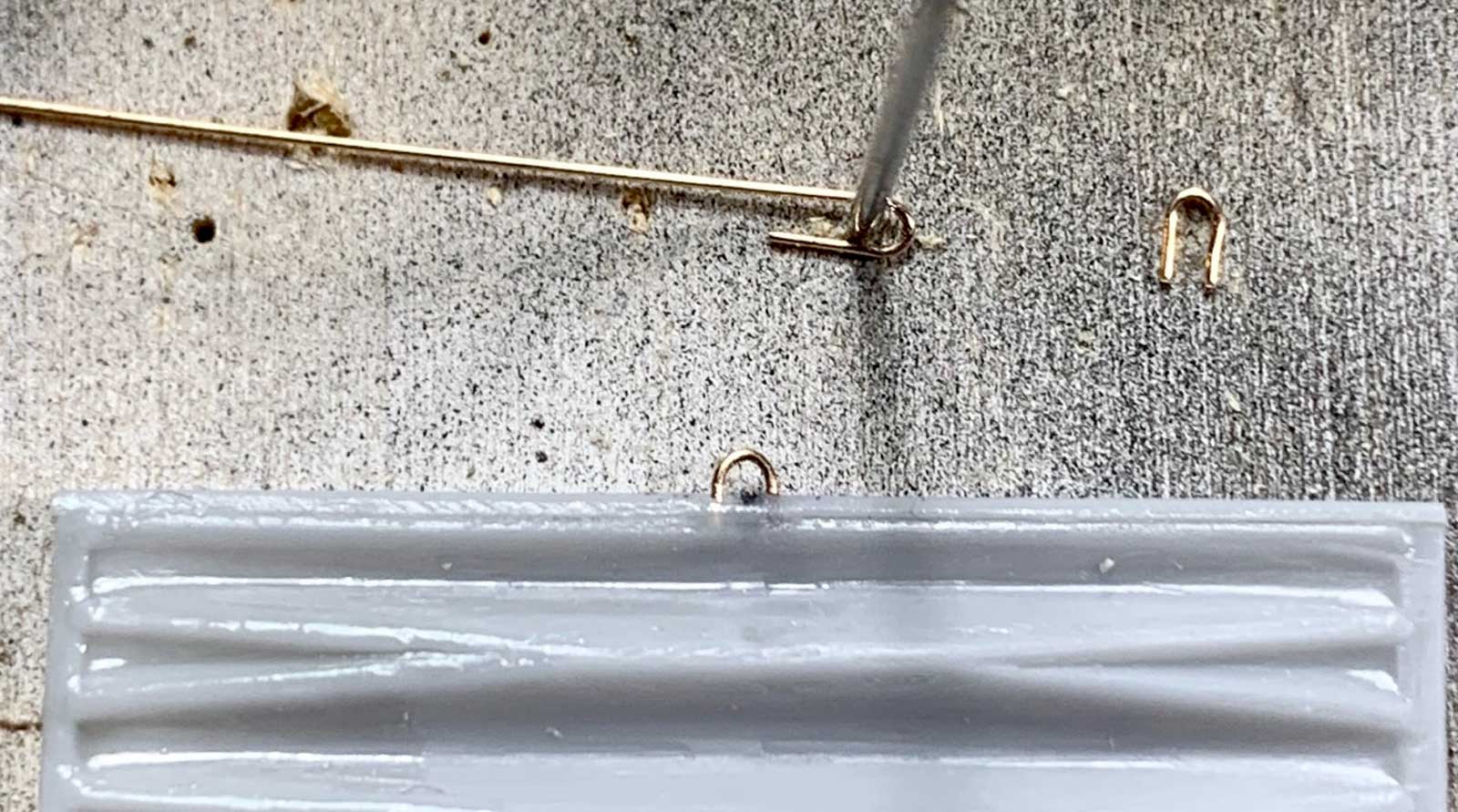
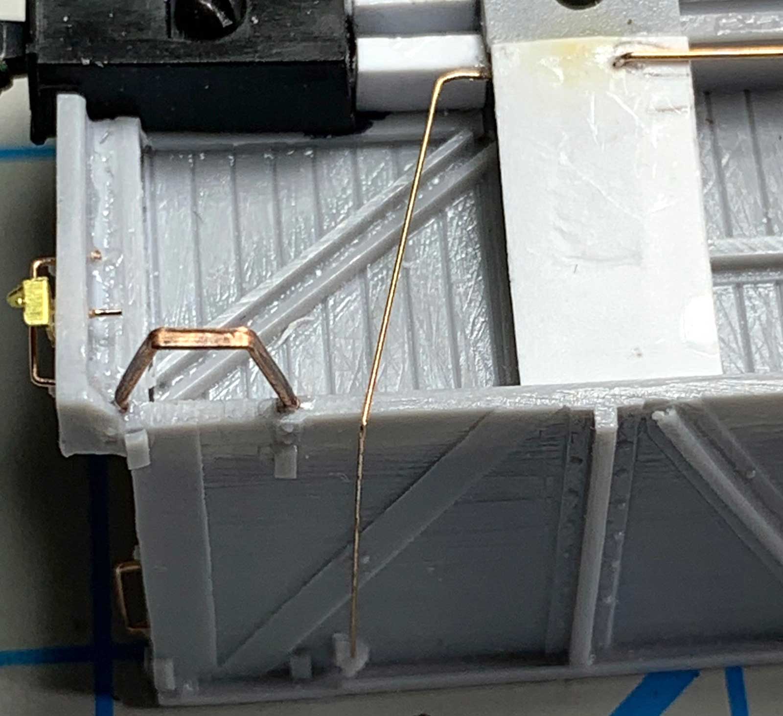
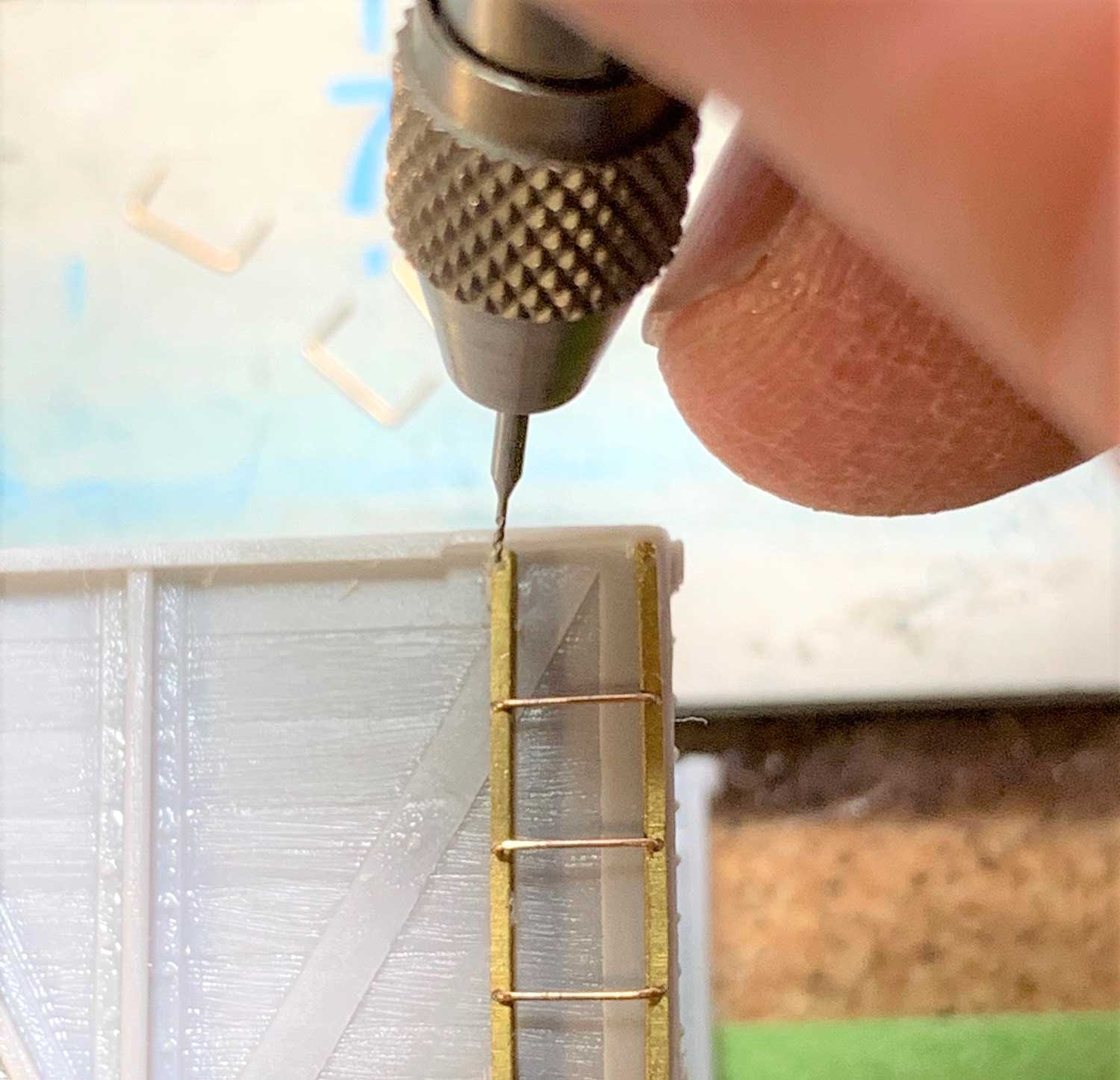
I installed the wire loop detail on the top of the ends. I formed 0.010-inch diameter brass wire around a 0.030-inch drill bit for a U-shaped loop. A 0.011-inch micro drill bit was used to carefully drill the somewhat delicate and thin end casting.
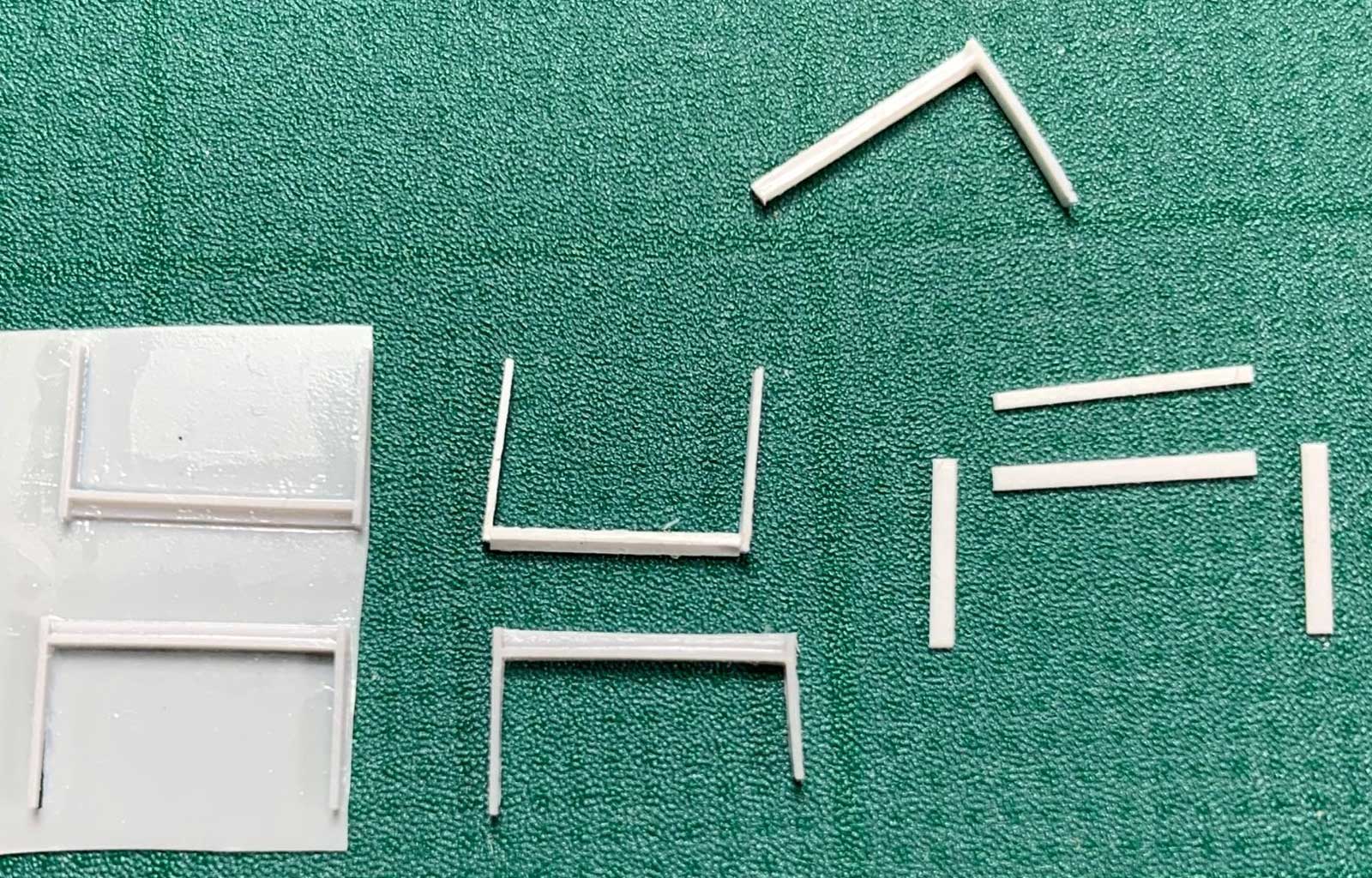
An interesting underframe details are the door stops for the drop doors. In the above photo, a couple are on the resin parts sheet. In the middle bottom is a full length resin part and above that is a styrene version I made shorter to avoid interfering with truck swing. On the right are the four styrene pieces to construct the center L of 1×3 and 1×3. The two legs are 1×3. I determined the length by installing the trucks and measuring.
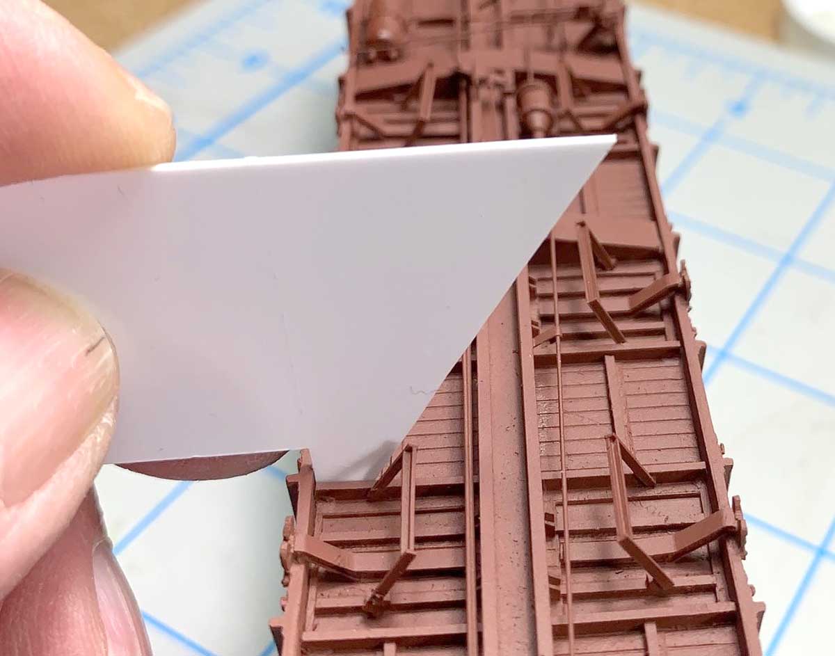
To properly mount the door stops, I made a styrene jig shaped with the proper angle and distance from the side to locate each one. My styrene jig is seen above after I had primed and painted the model.
I added the bleed valve rod next. I drilled a hole in the three-way valve and inserted a small eyelet made from #36 magnet wire twisted around a #80 drill bit shank. For the mounting on the other side of the car, I fashioned a bracket from 0.005 x 0.025-inch brass. I drilled a hole on each end and formed an L. The short leg of the L was pinned to the floor with 0.012-inch diameter wire. Cyanoacrylate glue (CA) secured the mount before I added the 0.008-inch diameter brass bleed valve rod.
The car was given a final wash in Dawn dish detergent. After it was dry, I sprayed a coat of Stynylrez Neutral Yellow Primer. The ends and floor will be installed after the paint and decal steps.
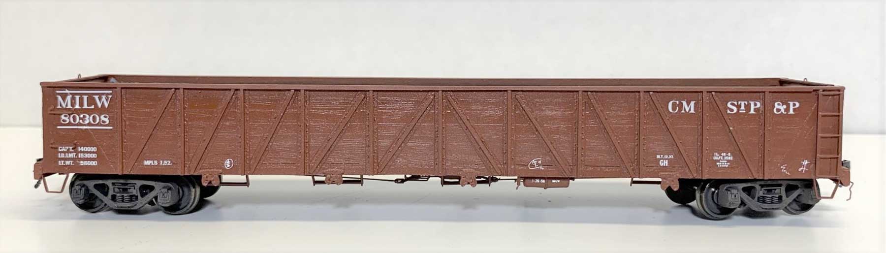
I used a new but old bottle of Polly-Scale Oxide Red on the sides and ends, then sprayed Future/Pledge acrylic gloss for the decal base. Decals were applied following photos in the instructions.
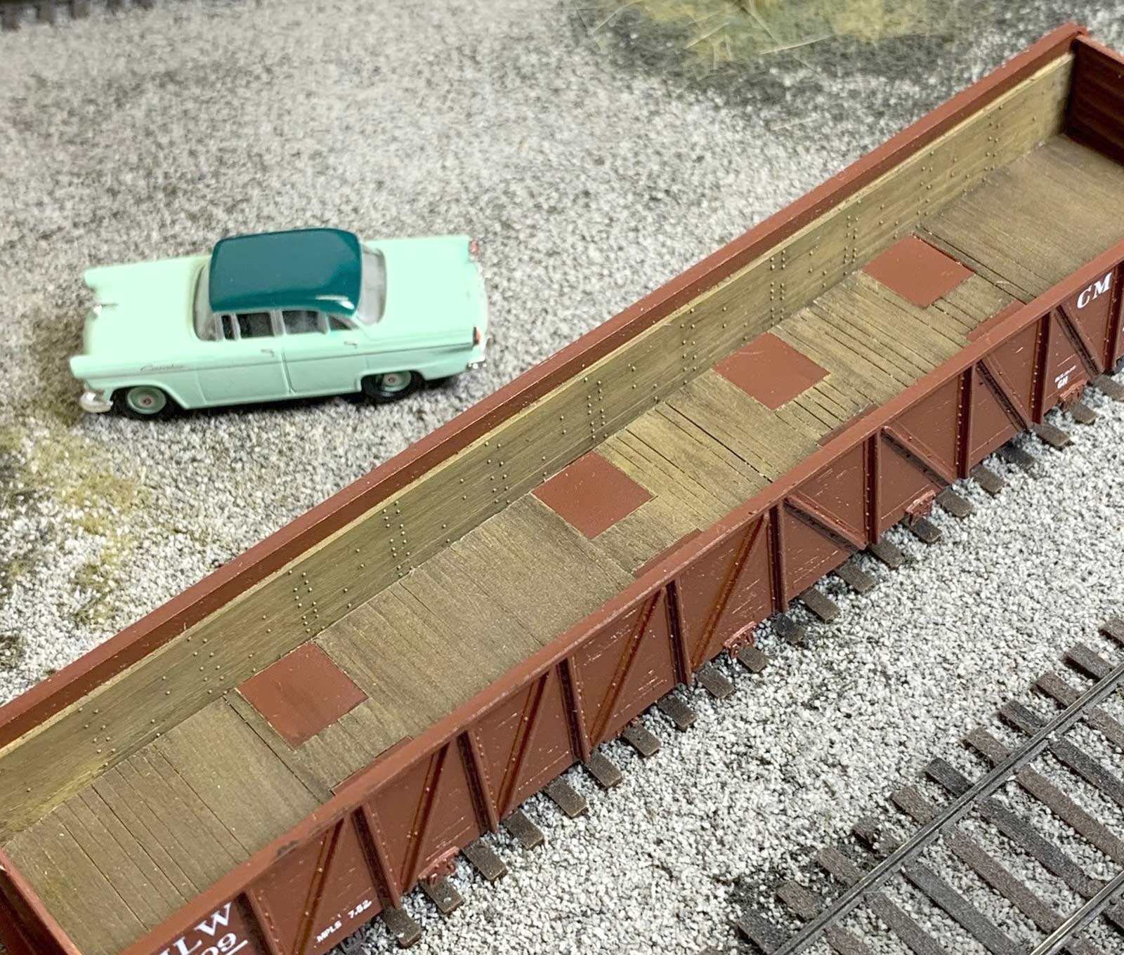
I painted the wood interior with varied tan, earth, and dirt colors. Once the interior was dry a wash of AK Interactive Brown Enamel Wash was brushed on and wiped off with cloth before drying. Further weathering will be added with Pan Pastels.
After applying the decals, the car was given a flat coat of Vallejo acrylic clear. More weathering will be added at a later date. I am practicing different wash methods and will post finished photos at a later time. I, too, am a Reluctant Weatherer.

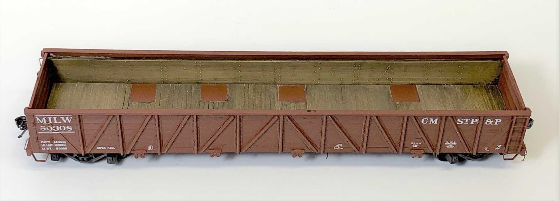
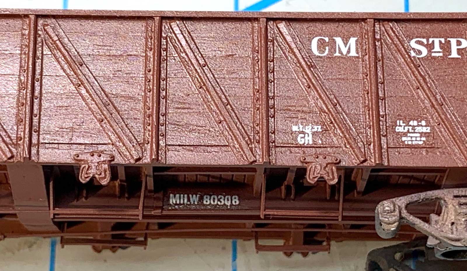
At long last, this Milwaukee Road gondola is ready for final weathering. You can see a couple of chips in the paint above the wood interior. I might just add some rust weathering to cover those spots.
Thank you, Frank Hodina, and the RCW minions, for producing these enjoyable to build kits.
That’s another inspiring model build. Thank you, George Toman, for sharing your fine model work. May we all take another step towards becoming better modelers.
Questions and comments can be posted below. Please follow the instructions so your comment can be posted. All comments are reviewed and approved before they appear. To subscribe to this blog, add your email address to the function at the bottom of the right column on the main page. Share the blog link with other model railroaders.
George, Another inspiring build. Thanks so much for taking the time and making the effort to share your work.
Rick Mink
Geogre
That is a superb build
Paul Doggett
Another fine build. Well done George.
Nice job!
George as always Another excellent build.
Lester Breuer
Outstanding!! I always enjoy seeing your work.
Steve Hile
Fantastic build George. Thanks for sharing
Fenton