We have another guest post this week. Eric Hansmann illustrates a couple of techniques to ease installing details onto freight car models.
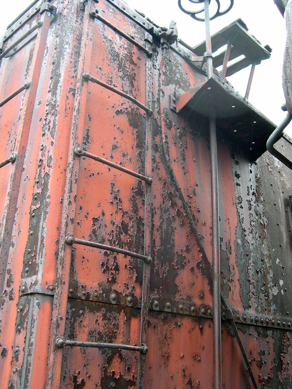
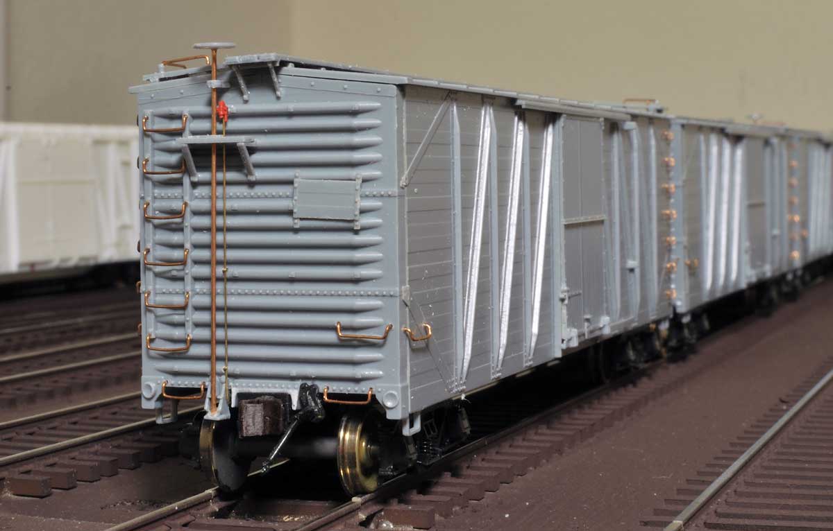
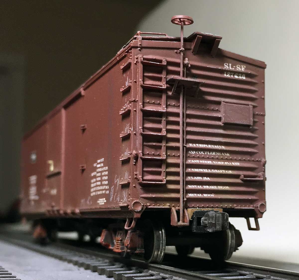
As prototype model railroaders, we often push our efforts to include many prototype detail elements on our freight cars. In reviewing the image above, there are several common elements that are typical of many kits. Let’s take a look at one of the smaller components and how to ease the installation process. Click on any image here to review a larger size.
Retainer Valve and Air Line
The retainer valve and associated air line are common components on many freight cars. In HO scale, these are small parts and some modelers choose to install only the retainer valve. I’ve been drilling this small piece and attaching a wire for a more secure installation. A key to this work is to drill a #80 hole in the back of the detail part while the piece remains attached to the parts sprue. After drilling the hole, glue a length of 0.012-inch wire in place with cyanoacrylate superglue (CA) and allow some time for the adhesive to set up.
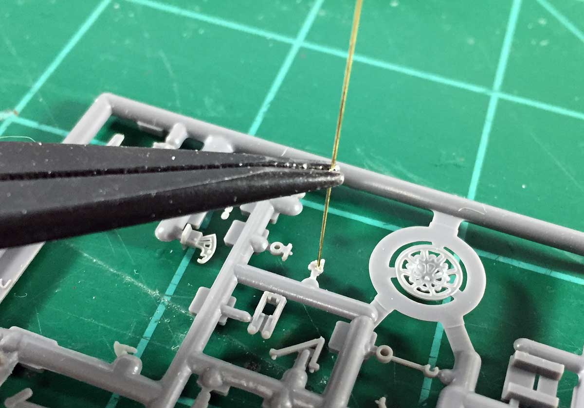
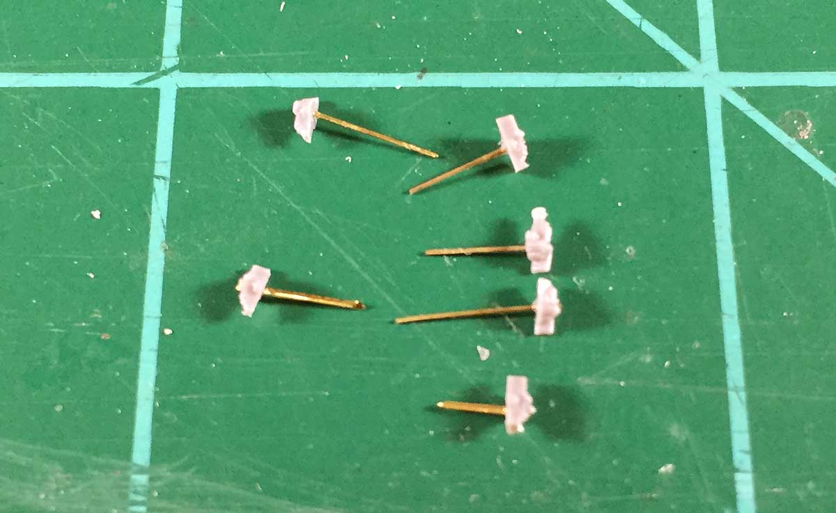
Carefully trim the part from the sprue and cut the wire just under a quarter inch long. It is easy to prepare several of these parts so they are ready for installation.
The retainer air line is a smaller size pipe than the other air pipes used on the prototype. In HO scale, 0.008-inch wire can be used to model this detail. The air line often runs from the retainer valve down the car end and disappears under the end sill. There are usually one or two anchor points that keep this line in place on the car end. The same 0.008-inch wire can be used to create these anchors.
You can make small hooks from the wire by bending it around a single edge razor blade. To make a hook, hold one end of the wire on a flat work space and place the razor blade across a small portion of the end. Press down with the blade to clamp the wire to the work surface and carefully bend the wire over the blade. I find the non-working side of the razor blade will give the hook the right profile to anchor the airline. Your first couple attempts may not work out, but a small portion of the wire is being bent so just clip off the end and try again.
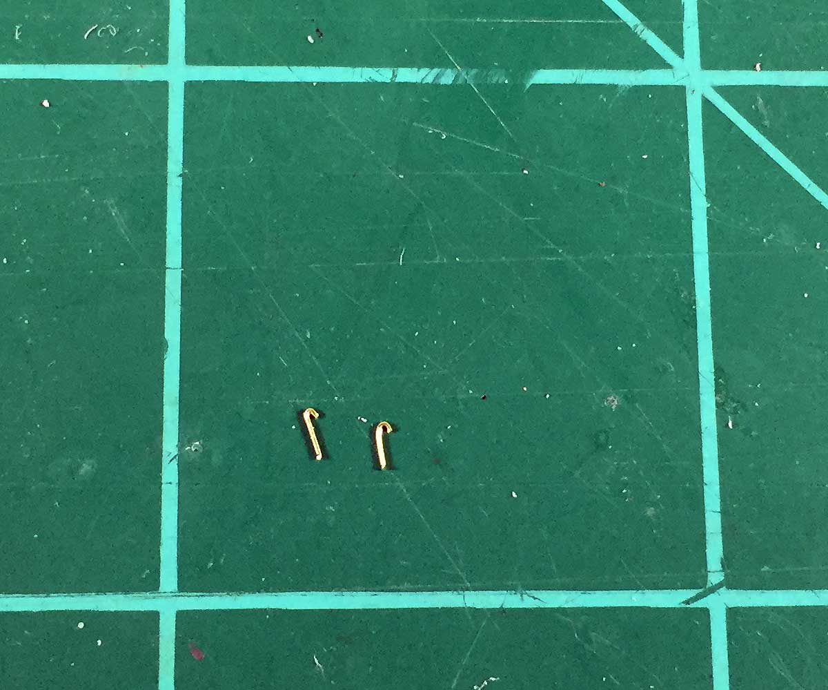
Once you have a nice hook, trim the short portion to make a shallow end, then cut the hook about a quarter inch in length. Now you are ready to install the retainer valve and the air line. Drill a #78 hole where the retainer valve will be place and drill #80 holes for the air line anchors. Before drilling, use a sewing needle to press a dimple onto the model surface at the appropriate points as a starter location for the drill bits.
Using a full strand of the 0.008-inch wire, bend the end to a 90-degree angle with about an eighth-inch on the short length. Add any other bends to this wire to reflect what is installed on the prototype. Place the short end of the air line wire in the hole for the retainer valve then place the retainer valve wire into the same hole. Apply CA from the backside if possible. If not, then apply adhesive to the retainer valve wire before inserting into the hole with the retainer airline wire.
Once the valve is in place, the anchors can be installed. Carefully hold them with fine tweezers, dip the long end into a small puddle of CA then insert the anchor into the #80 holes. Make sure the hook goes over the airline wire and keep it against the car end until the adhesive sets. Repeat for the other anchor. Once these are in place, curl the air line under the end sill (or however it disappears on the prototype you are modeling) and trim the line.
AB Brake System Components
Lots of modelers avoid installing the piping between the brake components on their models. Once you start building more detailed resin kits, you may want to add the extra details. At first look, the work seems daunting. Let’s break things down into smaller parts to make this easier.
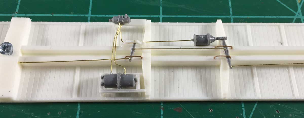
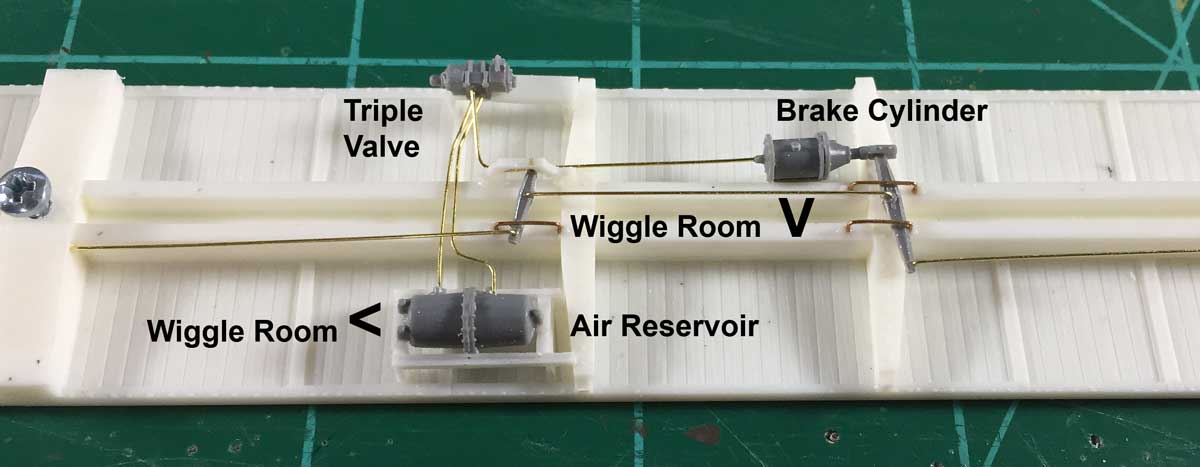
Understanding the main piping between components can lead to an easier installation. First, don’t allow the brake rods to confuse the picture. Concentrate on the brake cylinder, triple valve, and air reservoir. Note there are air pipes that run from the triple valve to the other two components. In many installations, the air reservoir is directly across the car from the triple valve so those pipes are mostly straight. The line to the brake cylinder makes a 90-degree bend and goes straight to the brake cylinder. Let’s start on these details.
First, remove only the brake cylinder and air reservoir from the parts sprue. Impress dimples onto the parts to ease drilling holes with a #79 bit. Many triple valve castings already have indents on the part. Identify those and then drill the holes. The triple valve is a small part. Only drill shallow holes for the wire installation. Cut a couple pieces of 0.012-inch wire about nine scale feet in length. Check the fit in the holes on the triple valve and use CA to fix these into place in the side by side holes.
The air reservoir and brake cylinder are larger castings. Take advantage of the size and drill the holes deeper into the parts. This gives you wiggle room for installing the wires that connect with the triple valve. Install the brake cylinder and air reservoir in the appropriate locations on the underframe and wait for the adhesive to set.
While waiting for these parts to set, bend a 90-degree curve in a length of 0.012-inch wire. This will connect the triple valve and the brake cylinder. Make sure the short leg of the wire is three to four scale feet. Set this aside to trim later.
Once the air reservoir is in place, remove the triple valve from the parts sprue and determine the location on the underframe. In many common installations, one wire will go straight across to the air reservoir. Trim that wire so it ends near the center of the air reservoir. The other wire will need a couple of bends to come into line with the other hole in the air reservoir. Both bends are typically on the same side of the center sill as the air reservoir is located. Carefully make these bends and check the wire length. Trim to a similar length as the first wire and slide these into place. If you are satisfied with the triple valve location and the bends in the wire to the air reservoir, then glue the triple valve into place and add a touch of CA to the wires entering the air reservoir.
Check the other wire that will connect the triple valve and brake cylinder. Trim the short end to fit the triple valve so the long end goes straight to the brake cylinder. Trim that long end so it extends into the center of the brake cylinder and install. Add a drop of CA to the places where the wire meets the brake components.
After installing these air lines between components, I find the brake rod components are a much easier addition to the underframe. For years, I tried to cut wire exactly to length to connect the AB brake components. Then I realized I could create some room to work if the holes in the air reservoir and brake cylinder were drilled deeper into the part. This has made the installation of the air piping between AB brake system components less tedious.
Thank you, Eric, for sharing your work here on the blog. Take time to visit Eric’s blog for his 1926 era HO scale freight car builds and layout operations. Questions and comments can be posted below. Please follow the instructions so your comment can be posted. All comments are reviewed and approved before they appear.
Great tips on installing the retainer valve and lines! These installs usually drives me crazy! Thanks.
Eric,
I like your approach to mounting the retainer valve & line. I’ll try it out on my next resin build. Thanks for the tip.
Isn’t it unusual that the brake rod to the A end truck runs on the right side of the center sill?
Thanks for stopping by Staffan! The underframe detail is part of a build for a Canadian Pacific steel sheathed “Minibox” car produced in HO scale by Funaro & Camerlengo. I followed the drawing of the underframe that was supplied with the instructions. I also reviewed Ted Culotta’s Essential Freight Car installment that covered these kits. Is something amiss with the brake rod placement?
I now see a component missing from the work on the blog image. The rod connecting the brake lever at the brake cylinder with the hand brake hardware. I should probably add that piece of wire. – Eric