
Jerry Hamsmith shares the final chapter of the box car group kit build.
The group building this kit (Ed Rethwisch, Bob Hanmer, Allen DeBraal, Jerry Zeman, and myself) focus on the B end and running board details, and the finishing touches.
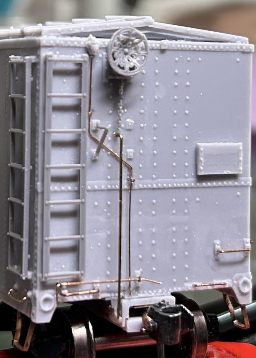
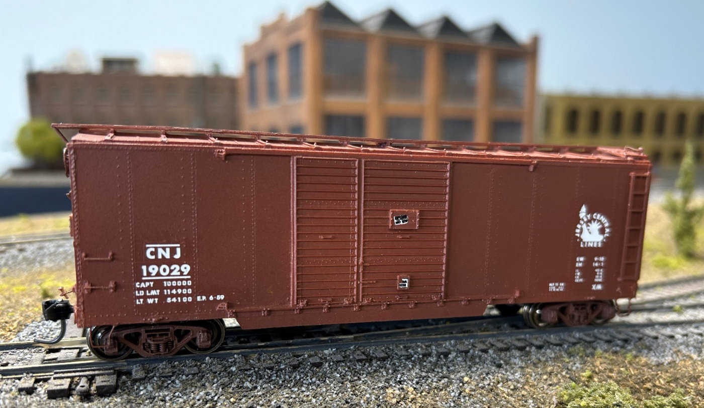
The previous post ended with the detail parts installation on the A end of the car. The lead photo shows the addition of the pin lifter. Some of the group members did not add this part until the very end of the build due to it’s fragility. Jerry Hamsmith added the pin lifter at this point. He drilled two #79 holes at the locations on the casting. Yarmouth Model Works eye bolts are included in the kit and they were inserted into the hole. Jerry formed a piece of 0.010-inch diameter wire and threaded it through the eye bolts. He made the final bend over the coupler after everything was glued in place with CA.
B end details
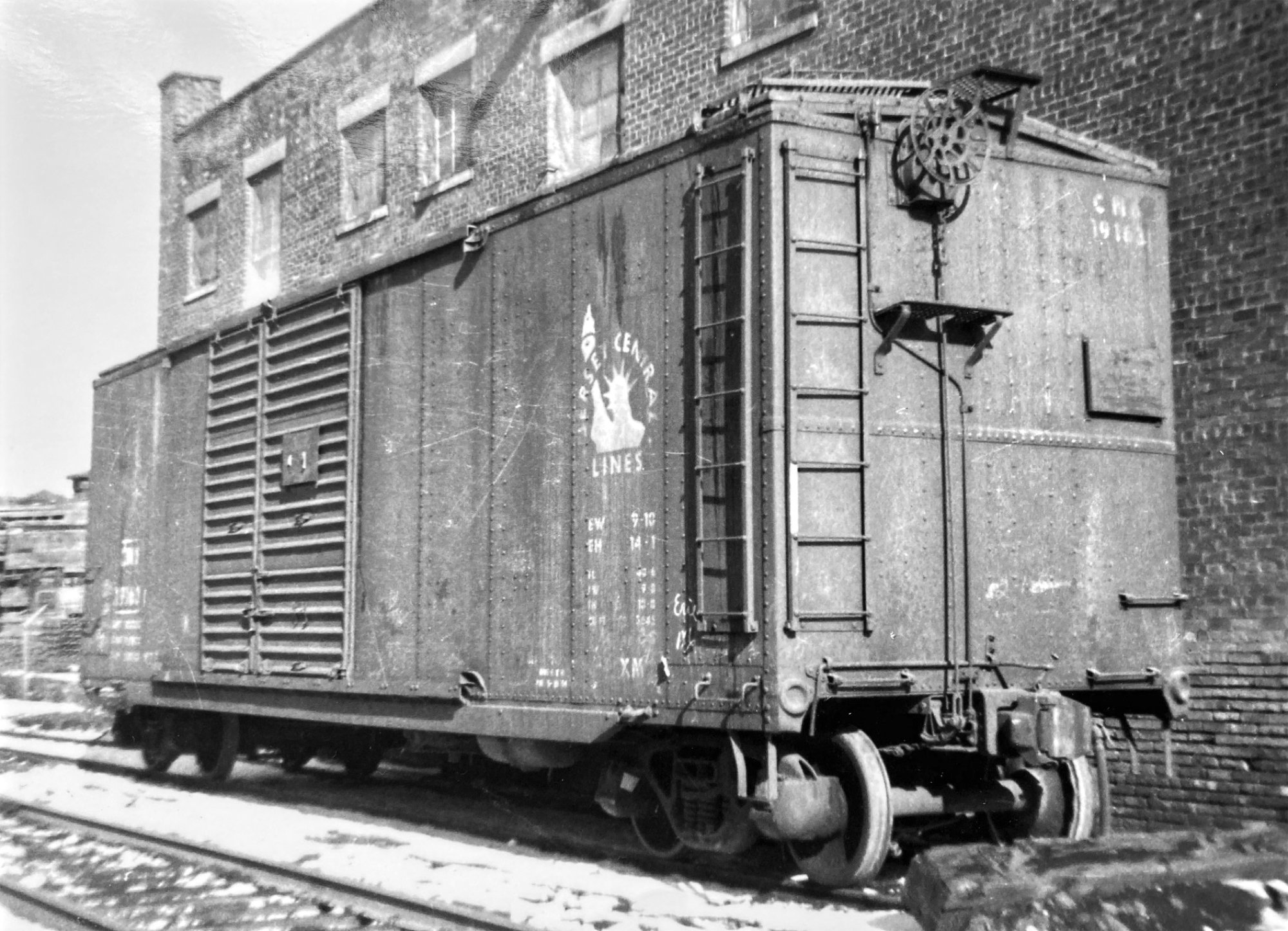
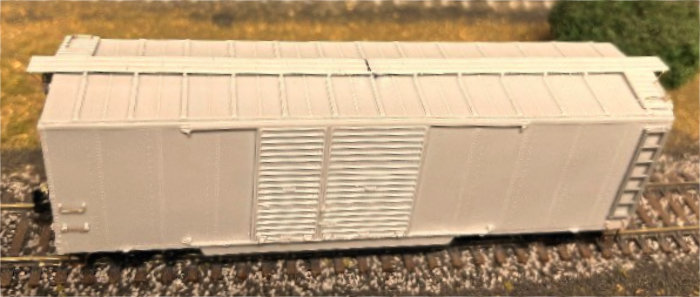
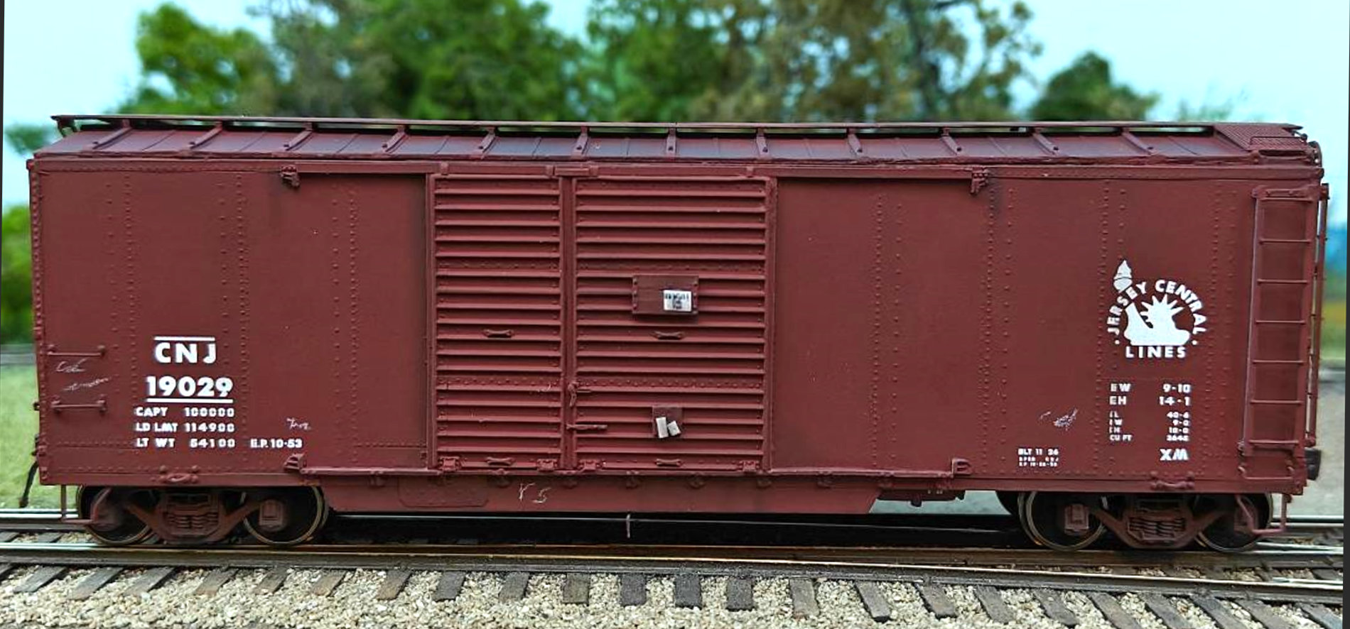
Although the above prototype photo shows ample space for the ladder, retainer valve and line, brake step and brackets, lower end grab irons, bell crank, and pin lifter, the model does not appear to have nearly enough space to fit all these things. So, an order was determined to add each of them that, hopefully, allows everything to fit into the space available.
First, as with the A end, the ladder, all the grab irons, and the placard board were added. The holes for the eventual attachment of the pin lifter were drilled.
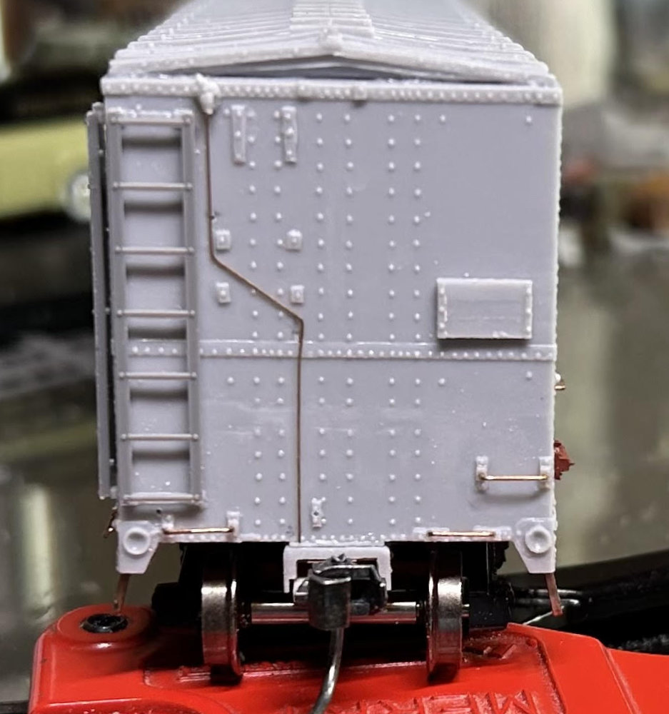
Next, the retainer valve and line are located closest to the car body, so they were attached next. The kit provided retainer valve was located per prototype photos and attached with CA. A #78 drill bit was used to drill a hole into the car end immediately below the center of the retainer valve. This becomes the anchor for the top of the retainer line.
The prototype has two supports for the retainer line and holes were drilled into the car end (#78) to eventually add these supports. A piece of 0.008-inch diameter phosphor bronze wire (Tichy #1100) was shaped to follow the prototype line. A small hook was created at the top of the wire and inserted into the hole below the retainer valve. Once the position of the entire line was set, CA was applied to the inserted hook. The very bottom of the line was also glued to the car end with CA.
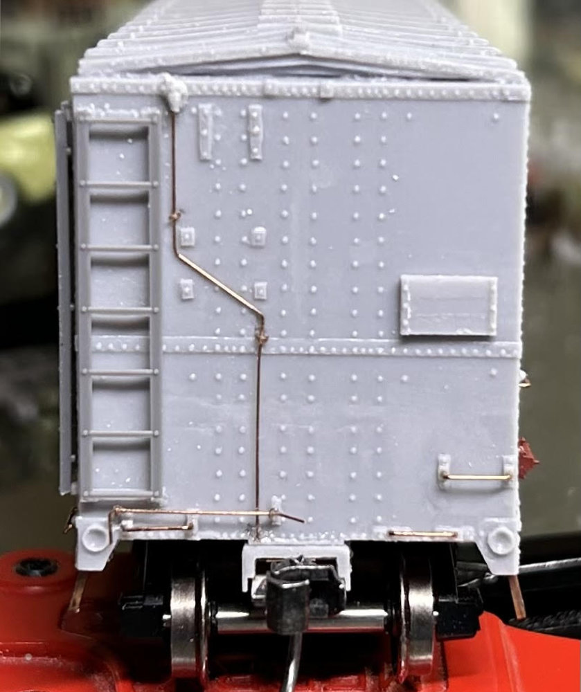
The pin lifter is the next detail. It was added just like on the A end of the model. The bend above the coupler was made after everything was set in place with CA.
The small supports for the retainer line were formed from unused portions of the Yarmouth Model Works eye bolt stems. One end was placed into the previously drilled holes and then the rest wrapped around the line itself. Once satisfied with the shape, they were nipped to length and glued in place with CA.
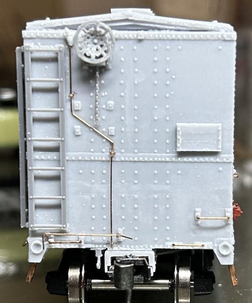
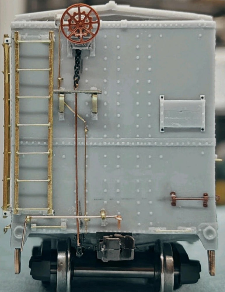
Using the Tichy parts (numbers in parens) provided with the kit the brake wheel (13), brake housing (16), brake chain (18), and bell crank (22) were added to the end.
The pre-cast housing supports provide the basis for aligning these B end parts. The vertical rows of rivets on the car end provide a guide for following a straight line. The bell crank was centered to the rivet rows first and glued to the bottom of the car end. The housing, wheel, and chain were all combined before attaching them to the car. The chain should be placed inside the housing so that there will be a space between it and the car end surface.
The chain will be shortened appropriately after the brake step and step supports are added. Also, a hole will be drilled for the brake stem wire at its top behind the brake step assembly.
The prototype photos show the chain ending just above the brake step and then a metal rod continuing to the bell crank. The connection of the chain to the metal stem could be modeled, or they could be combined behind or just below the brake step – out of sight. Jerry Hamsmith did that on his model. The rod is 0.0125-inch diameter phosphor bronze wire. The Tichy chain was shortened and a #78 hole drilled immediately below it. A hook was created at the top of the wire rod and inserted it into the hole as an anchor and also attached to the bell crank. The rod is separated from the car by a distance that makes it the outer most of the details at the bottom of the car end.
Ed Rethwisch followed a similar process on his B end details. However, he used a Kadee Ajax brake wheel (#2030) and Campbell 27 links-per-inch chain. He connected the chain to the brake shaft by looping the wire around a chain link. He made brake step supports from 0.010 x 0.018-inch brass strip bent to match the cast-on supports. The brake step is a Yarmouth Model Works part (#381). The kit provided tack board was glued to a pair of 0.005 x 0.060-inch styrene strips, then glued to the car. The rivet detail was created from harvested Athearn rivets.
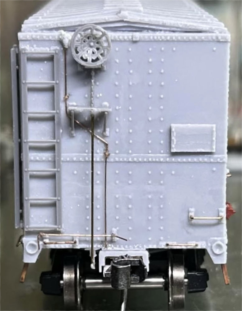
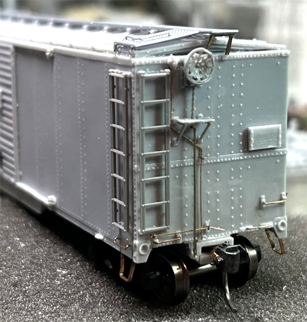
Jerry Hamsmith finished off his B end by using the Tichy brake step and supports. Following the prototype photos, the step was shortened so it extended just beyond both supports. The step clearance hole was enlarged to allow the easy passage of the chain. Jerry doesn’t add angle cock or air hose details to his builds. This is his finished car end.
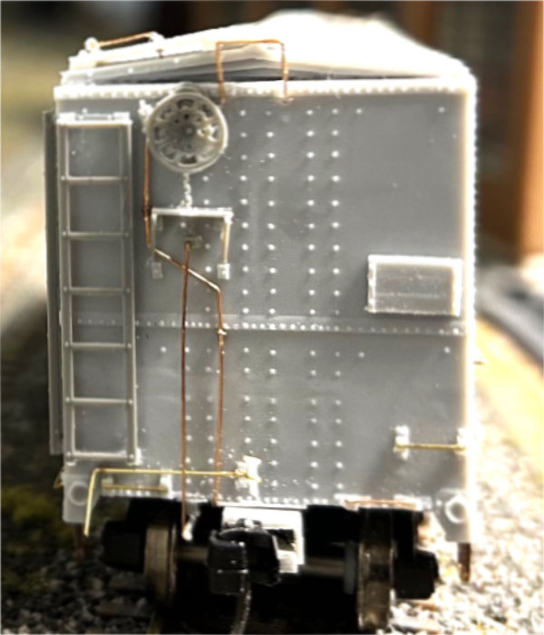
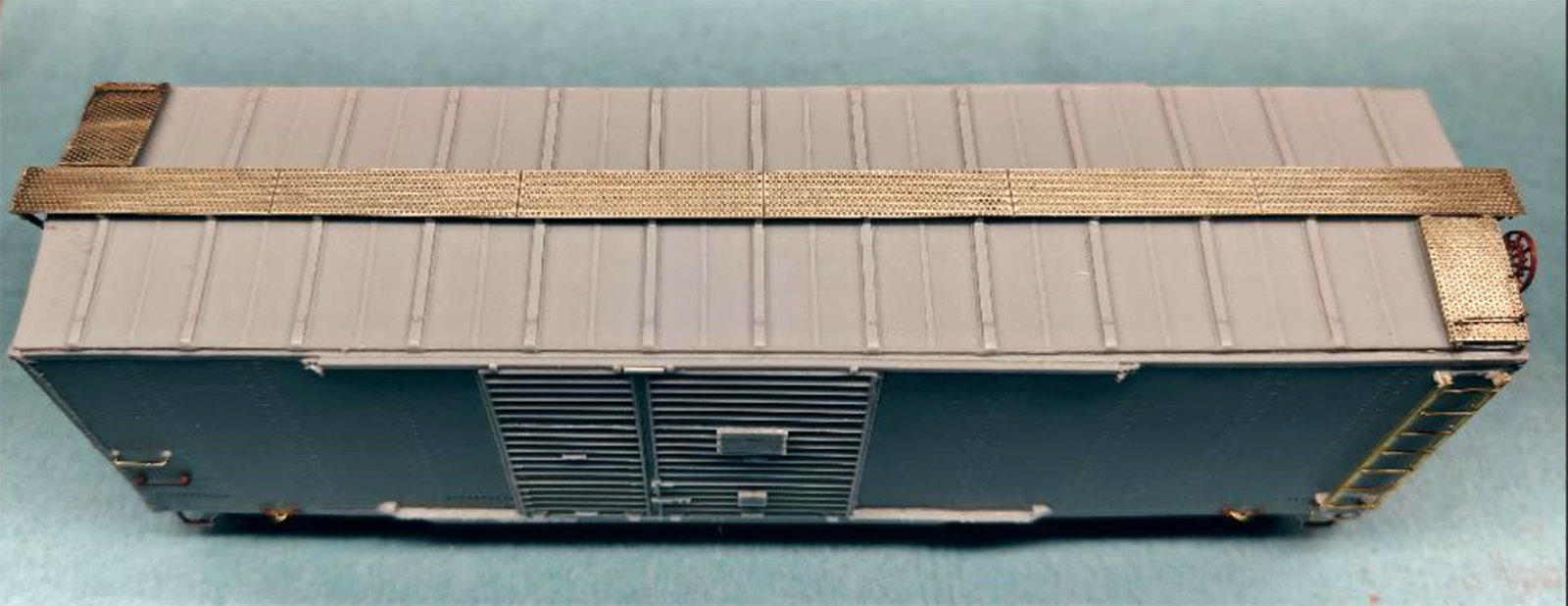
Allen DeBraal also used the Tichy parts for his brake step and supports. He snapped a completed B end photo after the running boards were installed.
Running boards
Allen installed a wood running board for his build. The CNJ was transitioning from wood to metal running boards as the cars were shopped during the early 1950s. Allen models 1952 and decided his car had not yet been updated.
Jerry Hamsmith models 1955 and chose to utilize a Morton steel running board. He used a Kadee (#2008) part. Before applying the part, the tabs on the bottom of the running board and on the end running board supports were removed. The laterals were bent slightly to follow the roof pitch.
To glue the Kadee part to the car, dabs of canopy glue were placed on the central seven supports on the roof. The running board was centered from end to end and side to side. The initial canopy glue was allowed to set slightly so the board no longer slid around. Then the ends of the running board were gently lifted and more canopy glue was placed on the remaining roof supports. The laterals were glued in place by applying CA to the lateral supports at the roof edge. Additional CA was sparingly applied to the entire length running board to ensure a permanent attachment.
Jerry used scrap pieces salvaged from the Yarmouth eye bolts brass fret for his end running board supports. They were cut to a scale 15 inches and applied with CA.
Ed Rethwisch used a Yarmouth Model Works (#252) etched metal Morton running board and mounted it similarly. This part comes with the end mounts for the longitudinal board as well as those for the laterals.
Finishing
Once everyone had completed building their models, group members proceeded to paint and weather their cars.
Allen DeBraal used Modelers Paint and Decals Box Car Red Acrylic Airbrush Paint on his car.
Ed Rethwisch first used Tamiya light gray primer and then Tru-Color CNJ 1940-50s Freight Car Red (TCP-210). The car was lightly weathered with oils and pencil marks used for the scribbled chalk marks.
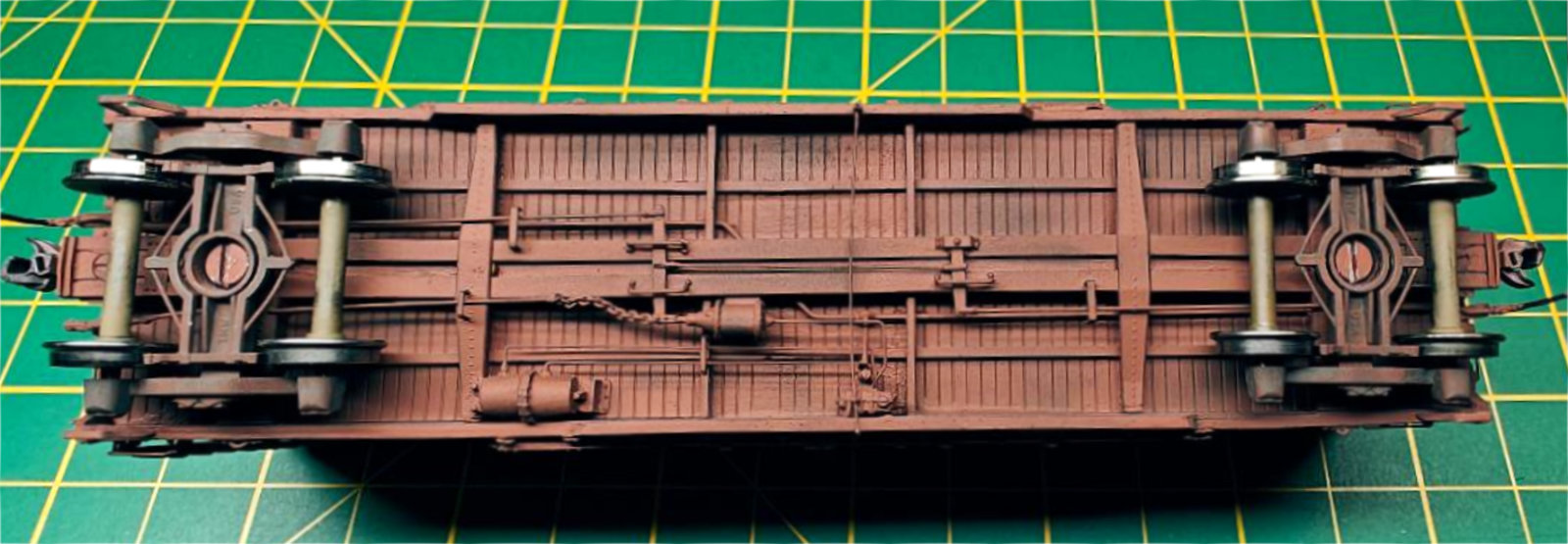
Ed also provided a photo of the painted underframe. He painted the trucks the same color as the car.
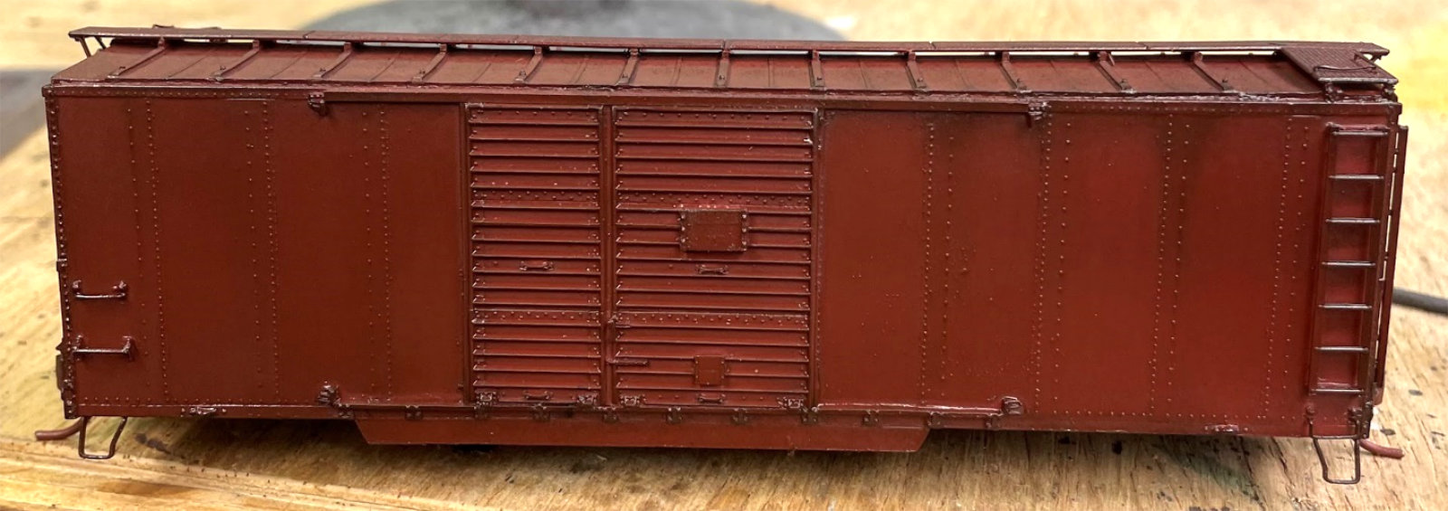
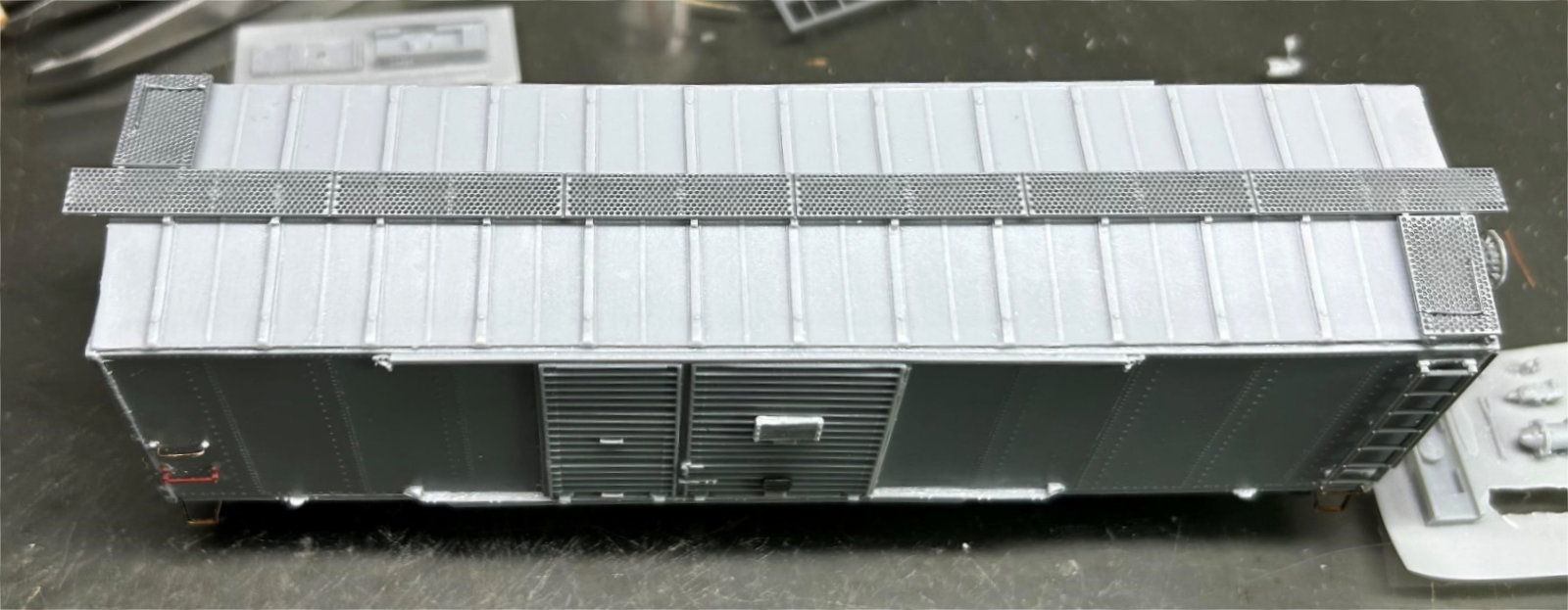
Jerry Hamsmith gave his car to Chris Vanko for painting and weathering. Here are two in-process photos of Chris’ work. The initial paint was the TCP-210 color. The photo above shows the car painted, pre-weathered, and glossed for decal application.
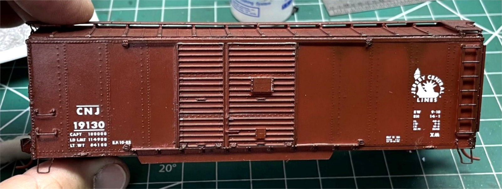
Here’s the car after decal application. A final weathering will be applied, as well as chalk marks, before it is ready for the layout.
We hope this summary of our various building processes was helpful and informative.
- Jerry Hamsmith
Many thanks to Jerry Hamsmith, Ed Rethwisch, Bob Hanmer, Allen DeBraal, and Jerry Zeman for sharing their progress and techniques on this Resin Car Works kit. Here are links to the previous Central of New Jersey boxcar group build parts.
We share these posts to inspire you to tackle a resin freight car kit. Maybe a few modeling friends will work together on a group kit build. It’s a great way to learn how these kits assemble and to add new freight cars onto your rails.
Subscribe to the Resin Car Works blog so you don’t miss a new model announcement. Add your email address to the Subscribe function at the bottom of the page.
Questions and comments can be posted below. Please follow the instructions so your comment can be posted. All comments are reviewed and approved before they appear. Share the blog link with other model railroaders.
Great project and I really enjoyed the different paths the builders used to get to the finish line. All the cars look very nicely done and the builders did a great job.