Category Archives: Details

Model Upgrades – 1

WRNX_5706_AC_web
A tank car model with components from Tichy and Athearn reflects a popular prototype.

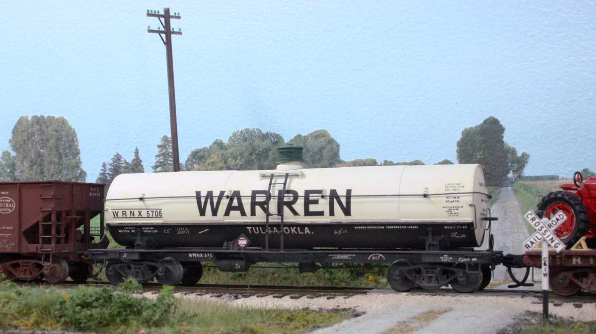
Here are a couple more modified models that are in service on the railroad. The Warren tank car is a shortened Athearn chemical tank on a lengthened Tichy frame. The cuts in the Athearn tank are covered with 0.005-inch sheet styrene to represent the jacket over the insulation. The model has the rough overall dimensions of an AC&F Type 27 Class 105 propane 10.5K gallon tank car. The bonnet is a resin casting that I did maybe two decades ago and has been noted several times on Tony Thompson’s blog. The decals are from Sunshine Models but others are available.

RI_90538_AC_web

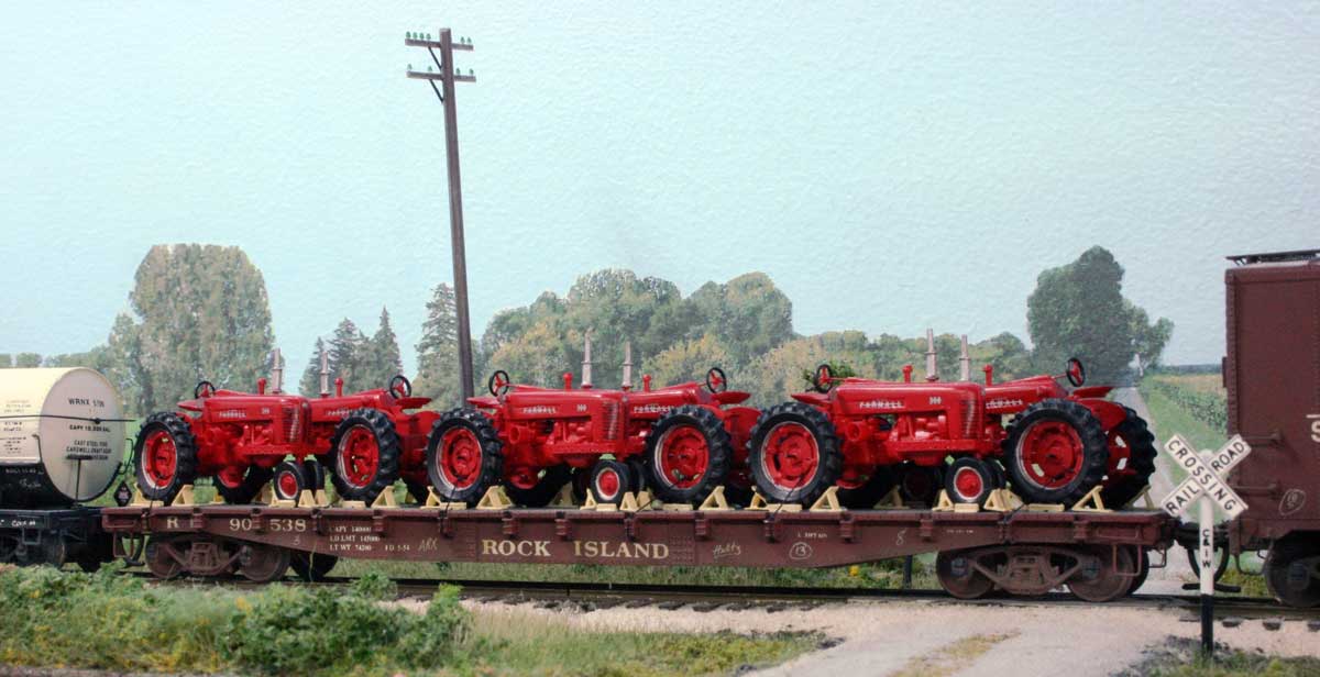
This flat car is actually two Red Caboose flat car models spliced together just as the Rock Island had done. Take a flat car, cut it in half, add new steel in-between and “presto!,” a longer flat car. The splice plates were done with styrene with rivets harvested from an Athearn gondola. Today we would use Archer rivet decals.

The decal lettering were extra bits from other used sets. The deck was widened with styrene matching the existing deck thickness and then distressed. The stake pockets came with the Red Caboose kits.

The load is six Farmall 300 series tractors which were produced from 1954 to 1956, which falls right into my late August 1955 time period. These tractors are resin castings from a pattern done for Martin Lofton at Sunshine Models, but were never issued.

A recent discussion on the Steam Era Freight Car YahooGroup centered on an interesting Waterloo, Cedar Falls & Northern (WCF&N) flat car. Here’s one way to model a similar prototype.

Frank

Oopsies

20150727_greytank_oops
It all looks great until the decals don’t fit!

I present for you a fine illustration of not paying attention to what you’re doing. In this example, I forgot to follow the measure twice cut once rule.

I was working on a build of Resin Car Works Kit 1.04. I painted the grey and masked that area, then painted the rest of the tank red. The lower tank, frame and trucks were painted separately then the car was assembled. When I went to place the decals, they did not fit.

You did read that correctly. The decals did not fit.

I had made the grey area too wide. This grey band shouldn’t be any more than the width of the platform. I would have known this if I had test fit the decals to the area before masking the car. So I lost some time on this build. I’ll just repaint the car in black, which is appropriate for my era.

It’s a lesson learned on this tank car paint job. I know I’ll get it right the next time!

Frank

How to Determine Rung Spacing When Scratch Building Ladders


Scratchbuilt ladders upgrade a model on Bill's workbench.
Scratchbuilt ladders upgrade a model on Bill’s workbench.

Bill Welch steps in for a post on a recent technique that moved a project along. Click on any image here to review a larger size. Enjoy his story.

Because so many Steam Era House Cars were not of a standard design, or were ad hoc standard designs, the ladder rung spacing on Box, Auto, and Refrigerator cars would have varied meaning for a modeler that the commercial ladders often available to us are not exactly correct. Having become fanatical about the proper shape of Sill Steps, it was only a matter of time before I became obsessed about ladders. For models I spend a lot of time on I have been scratch-building ladders. Initially and luckily I could do this using an HO scale ruler but then I encountered a situation that required a different way to calculate the rung spacing and was wondering how to do this. I floated an email to members of my Modeling Posse and Pierre Oliver remembered a solution from his High School Drafting class and what he described worked perfectly and is ridiculously easy. Here goes.

ladder_web

First off knowing where the location of the top and bottom ladder rungs and the distance between them is necessary and often there is a feature on the side of the car that helps us determine those two spots. From there we calculate the distance between them. Draw a straight line longer than you need and mark the line with two spots that correspond to the scale distance between the top and bottom ladder rungs. At each of those two spots draw a line at the same angle so that you have two parallel lines. I use 30° because it is easy but the angle really does no matter as long as both angles are the same. Okay, say you need an 8-rung ladder: Using either a compass or a ruler mark off 8 spaces on each parallel line. All marks must be equal distances. Then with a straight edge connect each set of dots or marks and like magic you have positions for each of the other six ladder rungs.

Rung spacing calculator.

The task ended up Easy Peasey with the help of this drawing. The model isn’t quite done, but the ladders are complete and the build moves forward.

MILW_6505_web

Bill Welch