Jerry Hamsmith has been working with a group of modelers and each member is building a Resin Car Works NYC gondola kit. He sent notes and photos covering the work so far.
When Resin Car Works released this kit, I was intrigued by Frank Hodina’s comment of how easy the build was. I suggested to some friends that we all purchase the kit for a virtual group build. I had three takers, so four of us planned to build along with each other and share our progress via text and email. Group members had different levels of resin kit building experience and I had hoped everyone would work together and make the build enjoyable for all. I believe this happened.
Due to work commitments and illness, the build together part of the venture did not work as I expected. However, all four of us eventually built the kit. The following chronicles our steps.
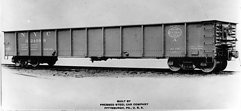
This three-quarter view of NYC 324099 was published in the 1931 Car Builders Cyclopedia. Note the towing staple on the side of the car at the bottom edge. Its application is slightly off center, appearing in the sixth panel from the B end of the car. The location of the towing staple on the other side of the car is unknown. I assume it is also offset. The staple is attached to the car via an L bracket.
The RCW kit represents cars with the drop doors removed so the door hardware is not modeled. Also, the car number was changed by simply replacing the first three numbers on all the converted cars.
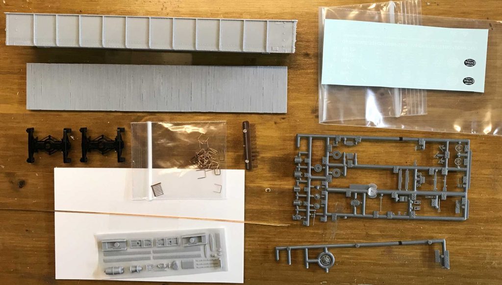
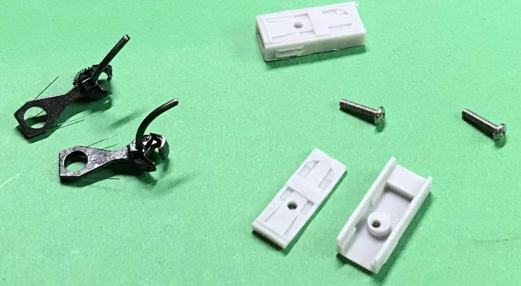
Here are the kit parts. Couplers are not included but scale coupler boxes are provided to use with Kadee #158 couplers. A builder must also provide wheel sets and styrene for the top chord stiffener if you model the car beginning in the late 1940s. A wood floor casting is provided, although many cars were rebuilt with a steel floor. The data for a steel floor was not available when the kit was in development.
Parts are included to model a vertical staff hand brake or a power hand brake. Although no weight is provided, a flat weight could be easily sandwiched between the body and the floor. The instructions, extra prototype photos, car renumbering info, and data sheets are available on the kit extras page.
After reviewing the instructions, the casting nub was removed from the floor and the detail parts were deflashed. Sprue nippers removed most of the nub. The remaining material can be sanded flat.
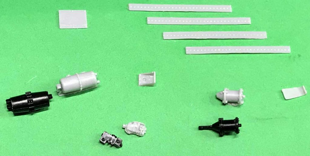
The black brake components in this image are Cal-Scale brake parts that I decided to use in place of the kit provided parts (also shown). Some of the build group used the kit provided Tichy AB brake parts and others used the resin parts.
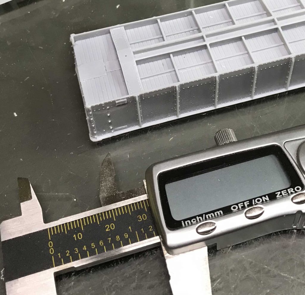
I spotted and drilled holes for the trucks next. These should be centered 39/64-inches from the inside edges of the car body sides and 11/16-inches from the end of the car. The above image shows a #78 pilot hole drilled at the mark. A #50 bit (0.070-inch diameter) was used to drill the holes and then tapped with 2-56 tap. I installed 3/8-inch long 2-56 screws.
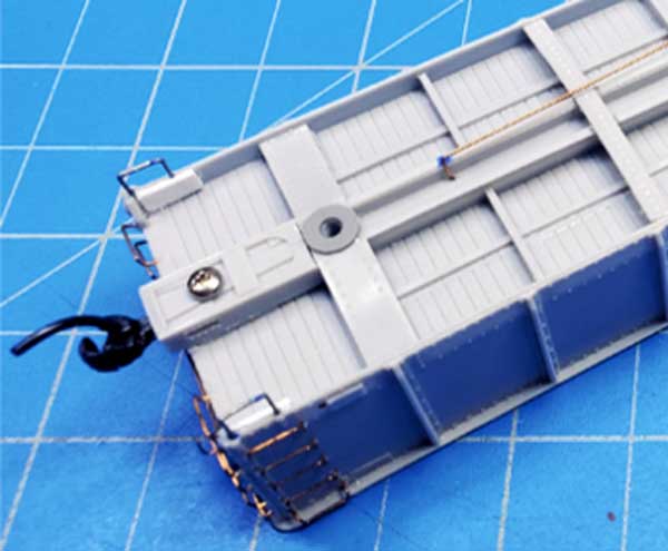
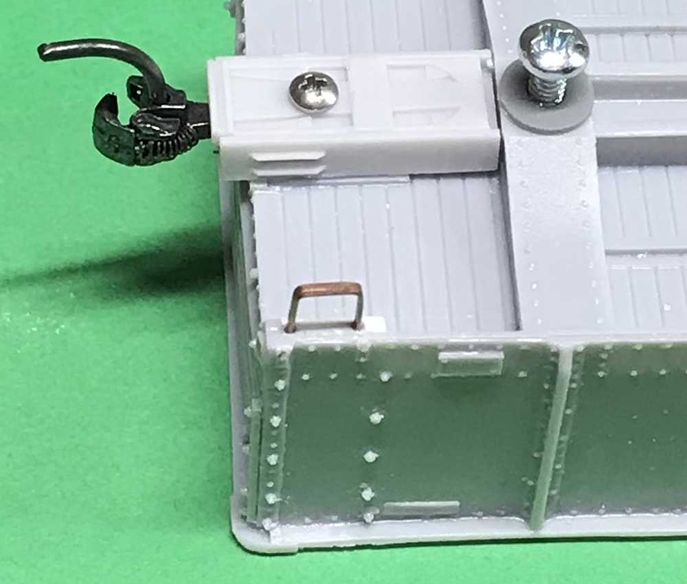
After cleaning up the kit provided coupler boxes, the lids were placed onto the boxes and a #56 (3/64-inch) hole was drilled completely through the box and into the underframe. An 0/80 screw holds the box in place. The couplers shown in the photo are Kadee #158.
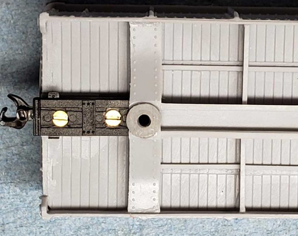
One of our group members installed Accurail Proto:HO scale couplers, so this gearbox and coupler were fit into place. Again, 0/80 screws were used to attach the box to the body. Any excess length of the coupler screws and/or the truck screws should be clipped off using a compound side cutter.
In reviewing the underframe photo in the instructions, note the bolster has a washer applied over the mounting hole for the trucks. This can be installed from the parts selection.
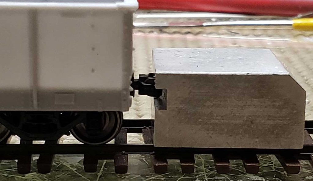
At this point, the trucks are installed to check drawbar height. I found my model sat slightly low. The Tichy brake sprue included in the kit contains two washers that I used over the bolster mounting holes. A recheck indicated a proper height.
Weight was glued to the car next. The image here shows a piece of lead that was cut and shaped to fit the car. A weight from an old Athearn 50-foot box car also fits the space and provides ample weight. Attach the weight with Formula 560 or similar adhesive.
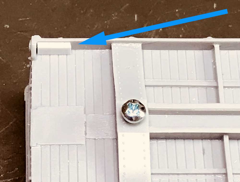
To mount the sill steps, a piece of 0.040 x 0.100-inch strip styrene is handy. Small pieces were cut and glued to the inside corners of the underframe, laminated to the back of the side sill.
Holes were drilled into the styrene with a #70 bit and A-Line type A sill steps were installed. Drill these holes slightly oversize and make sure to trim the mounting legs on these parts to a shorter length. The prototype steps appear to extend a shallow distance from the sill. Mount the sill steps accordingly to match the prototype length.
Next, trim the cross bearer covers to length and glue them to the main cross bearers on the underframe.
While waiting for others to catch up, I decided to drill the grab iron holes. The rivet head attachments of the prototype grabs are cast onto the kit body. After testing the width between the rivets with the kit’s drop grabs, I found the spacing to be slightly wider than the width of the grab itself. If holes were drilled directly below the cast on rivets, the grab iron parts would need to be stretched to fit into the holes. I drilled holes for the grabs slightly inward of the bottom middle of the cast-on rivets. This adjustment is not noticeable on a finished car and the grab retains a normal shape.
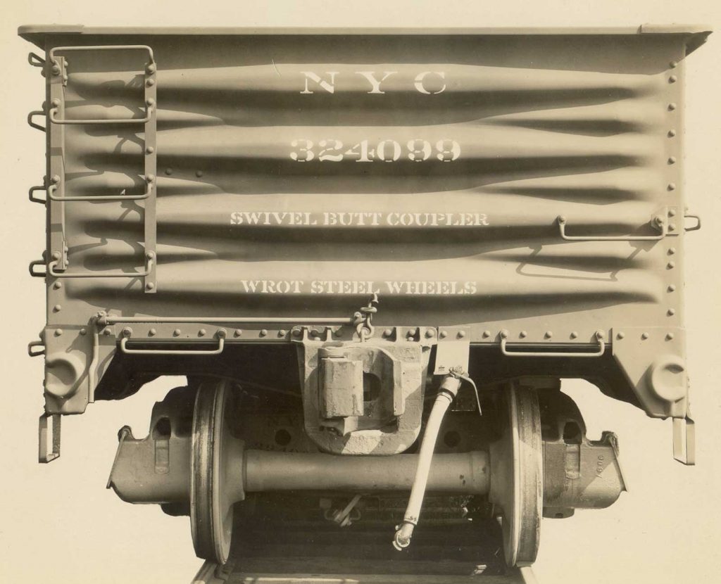
I found another caution when installing the top grab iron on the ends and side ladders. As you can see in the above photo from the kit instructions, the top grabs are reversed and do not extend above the top chord of the car. This reflects the prototype details. A true fit doesn’t scale down well when we use wire that is larger than scale size. Holes could be drilled above the kit rivets but the grab might extend above the top chord. The cast-on rivets could be shaved off for better grab iron hole location. These rivets could be left off or reattached below the grab iron legs.
You can also bend your own grabs to fit as an alternative to the kit parts.
I also found the kit provided end ladder styles are slightly long. Compare with the prototype photo and trim accordingly.
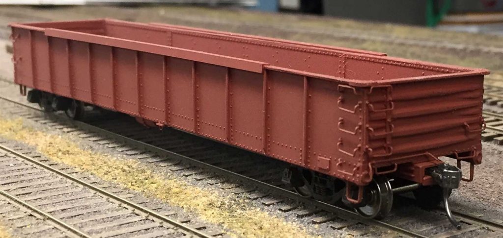
I carefully installed a few of the grab irons to ensure they did not protrude into the inside of the car body. This image helps you see the grab iron work after the car color was applied. But I’m getting ahead of the project. At this point in my build, I waited for the others to catch up. I’ll feature the underbody brake system details in an upcoming post.
Thanks to Jerry Hamsmith for sharing this build update. We will have another part of this project soon.
Questions and comments can be posted below. Please follow the instructions so your comment can be posted. All comments are reviewed and approved before they appear. To subscribe to this blog, add your email address to the function at the bottom of the right column on the main page. Share the blog link with other model railroaders.




Really good recap of the build! Darn it, now you made me want to build this car! Thanks for posting.
The angle iron on the sides is interesting. Is there a time frame for this modification? Great work Jerry!